Alternate Display Mode: While in the run mode (CTW and DTW = 0), you may use the DTW to vlew quan-
tities A and B. To view A. set DTW to 1. To view B. set DTW to 2. To view the quantity originally selected for
the Display, set DTW to zero. This does not affect the operation of the instrument. The values displayed
under A and B using this feature will always be full autoranging regardless of the setting of digit 1 of the
constant C12.
Function Indicators: These indicator lamps show the channel displayed.
4.4.2 Turning On The Power
1. Place the tachometer on the flat surface.
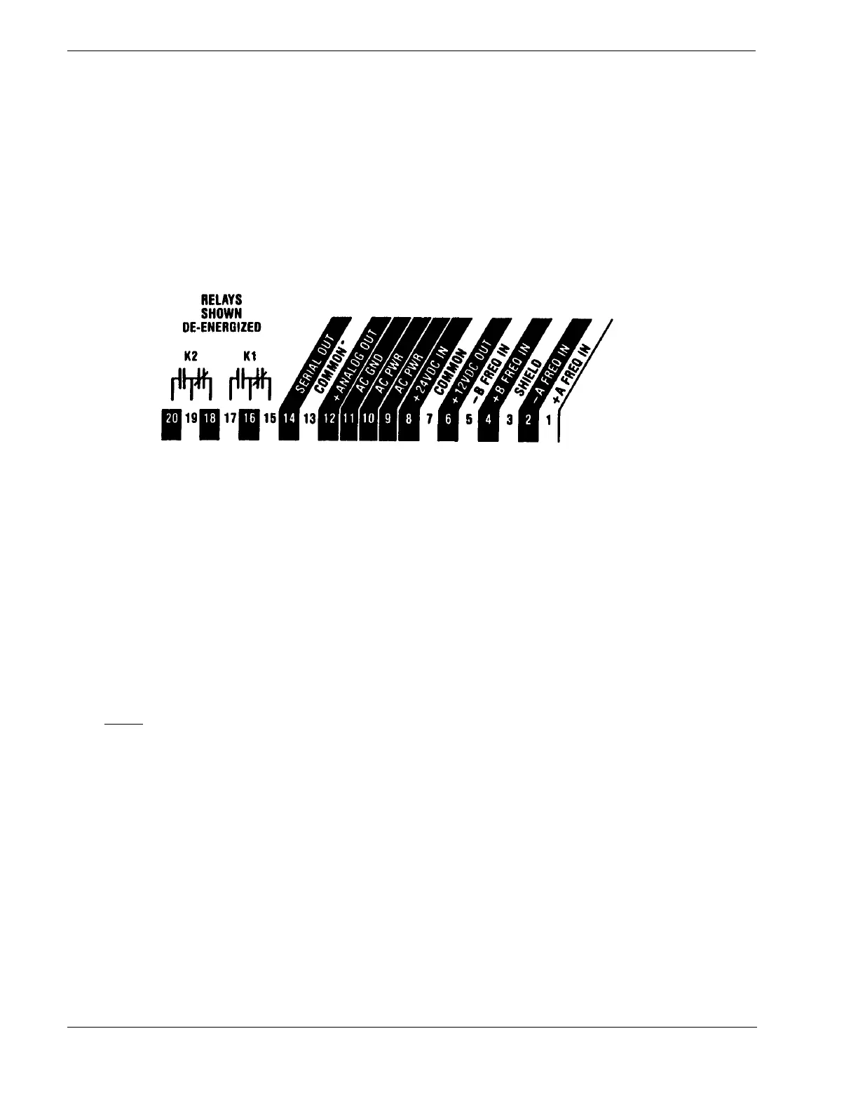
2. Attach the AC power cord to rear terminal lead 9,10, and 11.
3. Plug the unit into an AC outlet.
4.4.3 Entering The Scaling Factors For Frequency A and B (C1 thru C4)
Note: If you have a 60 tooth gear. then frequency is equal to RPM and the constants are equal to 1 (the
standard constant).
1. Use two 4 1/2 digit numbers in the form of a fraction to enter each of the scaling factors.
2. For Frequency A, enter the numerator in C
1 and the denominator in C2. For Frequency B, enter the
numerator in C
3 and the denominator in C4. If you are using the TACHTROL
®
3 tachometer as a single
channel instrument, do not adjust the settings for C3 and C4.
SAMPLE SCALING FACTOR
C1 = 19628,
C2 2500
To enter C1:
1. Turn CTW to 1
2. DTW is already set at 0. Push and hold the Pb until the decimal disappears.
3. Turn DTW to 1. Push and hold Pb until 8 appears on Display Digit 1.
4. Turn DTW to 2. Push and hold Pb until 2 appears on Display Digit 2.
5. Turn DTW to 3. Push and hold Pb until 6 appears on Display Digit 3.
6. Turn DTW to 4. Push and hold Pb until 9 appears on Display Digit 4.
7. Turn DTW to 5. Push and hold Pb until a 1 appears on Display Digit 5.
14
 Loading...