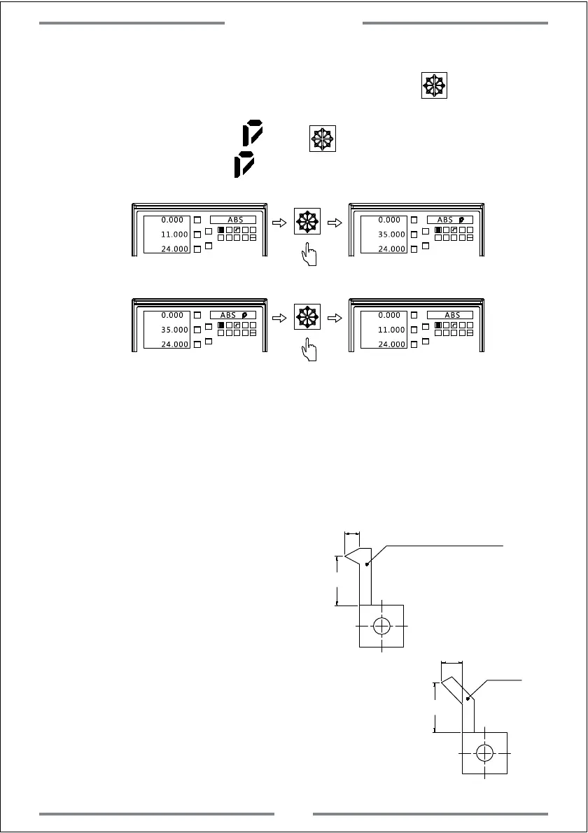
When 3 axis DRO has been set to be lathe mode.Press ,the value
of Y and Z axis can be summed and displayed on Y axis,while the right
window will display mark .Press again to get back to normal
displaying,and the mark will disappear.
X0
Y0
X
1 32
-
+
CLS
Arc
sin
TOOL
0.000 ABS
11.000
Z0
24.000
Y
X0
Y0
X
1 32
-
+
CLS
Arc
0.000 ABS
35.000
Z0
24.000
Y
X0
Y0
X
1 32
-
+
CLS Arc
0.000
35.000
Z0
24.000
Y
X0
Y0
X
1 32
-
+
CLS Arc
0.000 ABS
11.000
Z0
24.000
Y
sin
TOOL
sin
TOOL
sin
TOOL
4.8 Axis Summing(Applies to 2 axis and 3 axis Lathe)
ABS
4.9 200 sets of tool offset(Applies to 2 axis and 3 axis Lathe)
During machining on lathe,different tools are needed for one kind of
work-piece.Finding the zero point again after loading and unloading tool
is time-consuming.For this,the DRO provides 200 sets of tool offset.
Note: This function is only applicable once lathe has been equipped with tool post.
1. Set a reference tool.After setting
well,zero the value of both X and Y axis.
Basic Setting:
30
10
25
20
figure A
Tool 1(Reference tool)
Tool 2
2. Confirm the position of Tool 2 according
to the coordinate difference between Tool
1 and reference tool.(Shown in figure A)
The position of Tool 2 can be calculated
as:X 25-30=-5,Y 20-10=10.
Special Function
35