3. Number the tool,and memorize its position data which is basing the
reference tool.
10
5
Tool 1
Tool 2
Tool 2
±
±
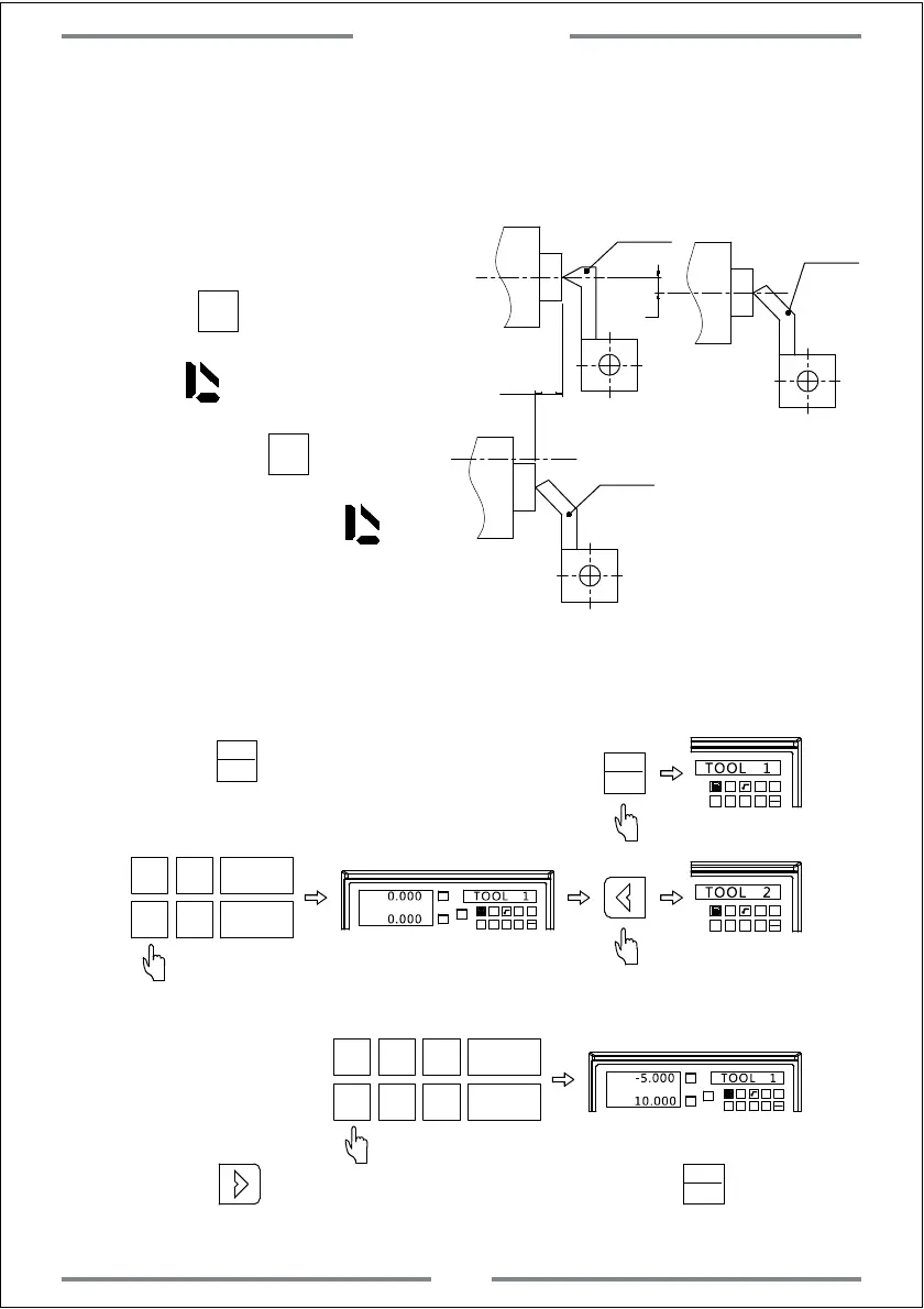
The operation of setting the tool are as the following:
Step 1: Move the tool 1 to zero point and zero the value.Set the tool 1 as
reference tool under ABS model.
Step 2: Press to enter the tool setting
1 32
-
+
CLS
Arc
sin
TOOL
TOOL 1
sin
TOOL
sin
TOOL
Step 3: Input the coordinate of tool.
1 32
-
+
CLS Arc
sin
TOOL
TOOL 2
X
0
T
Y
0
T
X0
Y0
X
1 32
-
+
CLS Arc
sin
TOOL
0.000 TOOL 1
0.000
Step 4: Input the coordinate of tool 2.
X 5
T
Y
0
T
X0
Y0
X
1 32
-
+
CLS Arc
sin
TOOL
-5.000 TOOL 1
10.000
±
1
Step 5: Press to input the coordinate of next tool.Press to exit the
tool setting.
sin
TOOL
4. When machining,user could input
or switch the tool number.Move the
carriage until the value of both X
and Y axis become 0.
5. Press 10 times.The right
window will display TL-OPEN with
a mark .This indicates the tool
offset function has been
activated.Press 10 times
again.The right window will display
TL-CLOS,and the mark
will disappear.This indicates the tool
offset function has been turn off.
figure B
Special Function
36