X0
Y0
X
1 32
-
+
CLS
Arc
sin
TOOL
Z0
Y
1 STOP
1
ET
X0
Y0
X
1 32
-
+
CLS Arc
sin
TOOL
Z0
Y
0 AUTO
0
ET
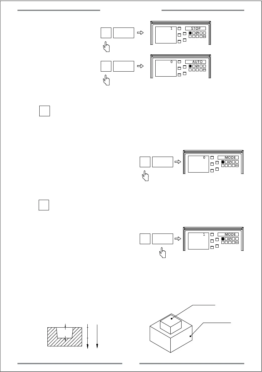
Manual exit
Automatic exit
Step 5: Select the EDM machining mode.The defaulted is mode 0.
Press to select mode 0.The output of relay are shown as below:
a. When power off,the relay coil is OFF.
b.When the CPU is not initialized,the relay coil is OFF
c. When output 1 under normal status after
the DRO power on,the relay coil is ON.
d.When output 1 once the EDM function
has been activated,the relay coil is ON.
e.When output 0 once the target height has been reached,the relay coil is OFF.
0
X0
Y0
X
1 32
-
+
CLS Arc
sin
TOOL
Z0
Y
0 MODE
0
ET
Press to select mode 1.The output of relay are shown as below:
a. When power off,the relay coil is OFF.
b. When the CPU is not initialized,the relay coil is OFF
c. When output 0 under normal status
after the DRO power on,the relay coil is OFF.
d.When output 1 once the EDM function has been activated,the relay coil is ON.
e.When output 0 once the target height has been reached,the relay coil is OFF.
1
X0
Y0
X
1 32
-
+
CLS Arc
sin
TOOL
Z0
Y
1 MODE
1
ET
4. Example of positive direction machining
Example 1: Machining the work-piece shown in figure A
0
20
Positive
machining
direction
Z
Figure A
Work-piece and electrode are shown in figure B.
Confirm the machining direction as positive.
20
Electrode
Work-piece
Figure B
Special Function
41
 Loading...