Page 24
13 Remote Interface Operation (MX100TP only)
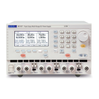
13.1 MX100TP Rear Panel Connections
Output Connections
The Output and Sense terminals are duplicated on the rear panel terminal block marked
Output +, Output -, Sense + and Sense -. These connections are paralleled with their front
panel equivalents.
Switch the front panel LOCAL/REMOTE switch to REMOTE when remote sensing is required.
When the rear panel output terminals are used, the use of remote sense is always
recommended to ensure that output regulation is maintained within specification; connections
can be made to either the front or the rear remote sense terminals but never to both pairs of
terminals at the same time. Switch back to LOCAL when remote sensing is not in use.
Interface Connections
Interface connectors for USB, RS-232, LAN and GPIB are mounted on the rear panel. These
are described in detail within the following sections.
13.2 Remote Interface Configuration
The MX100TP model can be remotely controlled via its RS232, USB, GPIB or LAN interfaces.
The GPIB interface provides full facilities as described in IEEE Std. 488 parts 1 and 2.
The RS232 interface communicates directly with a standard COM port.
The USB interface enumerates as a Communications Class device and interacts with
application software through a standard virtual COM port device driver on the PC. The
instrument firmware can be updated in the field via the USB port; see Maintenance, section
16.4 .