VF, DHT, AES Series Manual |
Refrigerated Air Dryer User Manual
5
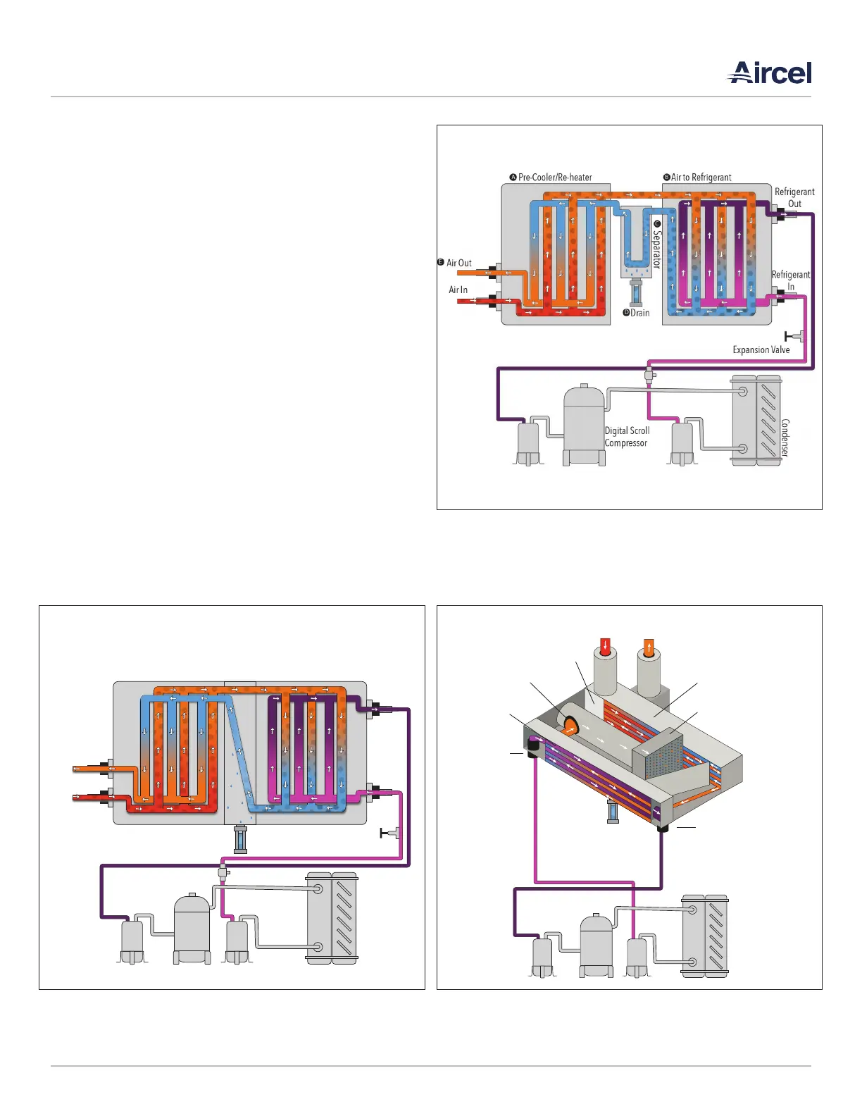
such as a reduction of the heat load imposed on the refrigerant
compressor and condenser, providing more energy to the
outlet air, and preventing condensation of moisture on the
outside of the plant distribution air line piping. From the air-
to-air heat exchanger, air will enter into the evaporator further
reducing its temperature to a desired pressure dew point.
As the air is cooled, moisture is condensed, separated, and
discharged through the condensate drain. The cooled air then
reenters the air-to-air heat exchanger, in a direction opposite
to the flow of the warm, saturated incoming air. This counter
flow action assures high temperature differential throughout
the heat exchanger, resulting in a more effective heat transfer.
Condenser
Compressor
Expansion Valve
Separator
Pre-Cooler/Re-heater Air to Refrigerant
Drain
Refrigerant
Out
Refrigerant
In
Air In
Air Out
Condenser
Compressor
Drain
Refrigerant Inlet
Air-to-Refrigerant
Heat Exchanger
Air Inlet
Pre-Cooler /
Re-Heater
Separator
Air Outlet
Air-to-Air Heat Exchanger
Stainless Steel Mist Eliminator
Refrigerant Oulet
FIGURE 2-2: TYPICAL SCHEMATIC FLOW DIAGRAM
VF Series 10 - 60; 1,600 - 2,000 scfm rated models
DHT Series 20 scfm rated model
FIGURE 2-3: TYPICAL SCHEMATIC FLOW DIAGRAM
VF Series 75 - 1,000 scfm rated models
DHT Series 40 - 125 scfm rated model
FIGURE 2-1: TYPICAL SCHEMATIC FLOW DIAGRAM
AES Series 600 - 10,000 scfm rated models