List of Figures and Tables
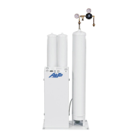
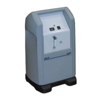
Figure 4.1: External Components — Front View 17
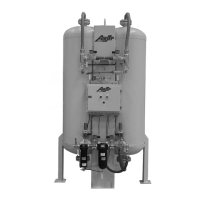
Figure 4.2: Manifold Components — AS-L Model 19
Figure 4.3: Typical Main System Control Screen 22
Figure 4.4: HMI Navigation Layout 24
Figure 4.5: Typical Oxygen Generator Screen 25
Figure 4.6: Typical Parameters and Output Screen 25
Figure 4.7: Typical Bed Pressure Graphs Screen 26
Figure 4.8: Typical Bed Pressure Calibration Screen 27
Figure 4.9: Feed Air Pressure Transducer Assembly 28
Table 4.1: Description of the Parts included in the Starter Kits 29
Table 4.2: Additional Available Accessories 31
Figure 5.1: Typical Installation Arrangement 35
Table 5.1: Feed Air Connection Sizes and Hose Sizes 35
Table 5.2: Oxygen Outlet Connection Sizes 36
Figure 5.2: Oxygen Sample Control Panel Connection 37
Table 6.1: Maintenance Chart 43
Table A.1: AS-D+ Specifications 56
Table A.2: AS-E Specifications 57
Table A.3: AS-G Specifications 58
Table A.4: AS-J Specifications 59
Table A.5: AS-K Specifications 60
Table A.6: AS-L Specifications 61
Table A.7: AS-N Specifications 62
Table A.8: AS-P Specifications 63
Table A.9: Typical System Set points 64
Figure A.1: Typical Pressure Profile and Valves Cycle Sequence 65
Figure A.2: Typical Installation Arrangement 66
Figure A.3: General Arrangement Drawing – AS-D+ 67
Figure A.4: Flow Schematics – AS-D+ 68
Figure A.5: General Arrangement Drawing – AS-E 69