Maintenance
2020 Flying Cloud 8-9
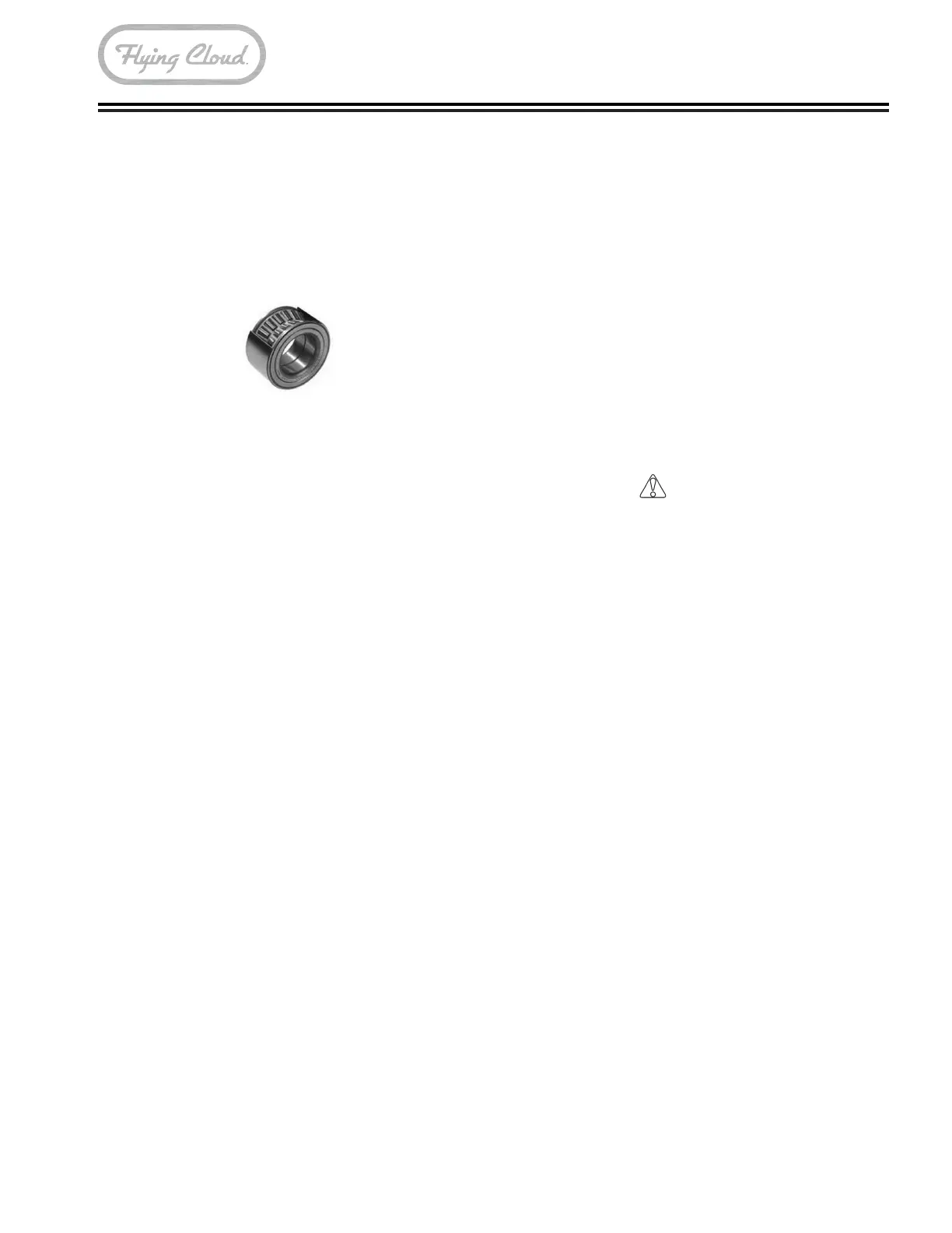
Nev-R-Lube Drums/Bearings
All Flying Cloud models are equipped with Nev-R-
Lube bearings. Dexter’s Nev-R-Lube bearings are
comprised of opposed tapered roller bearing cones
sealed inside of a precision ground, one-piece double
cup arrangement. These bearings are designed with
a small amount of axial end-play. The end-play is
essential to the longevity of the bearings service life.
Nev-R-Lube Bearing Inspection
1� Jack trailer at marked JACK location pad behind
axle on main frame.
2� Check for excessive wheel end-clearance by
pulling the tire assembly toward you and by
pushing the assembly away from you. Slight end-
play is acceptable (0.001 to 0.010 in.).
3� Rotate tire slowly forward and backward. The
wheel assembly should turn freely and smoothly.
4� Excessive wheel end-play, restriction to rotation,
noise, or bumpy rotation should be remedied by
replacing the bearing unit.
5� Bearing units should be inspected every year or
12,000 mi., whichever comes rst.
A slight amount of grease-weeping from the seal area
is normal. Excessive leakage may indicate abnormal
bearing operation. Bearing end-play inspection,
drum removal/installation, and bearing replacement
procedures are described in the Dexter Operation
Maintenance Manual enclosed in your owner’s packet.
Airstream recommends that these procedures are
performed by a qualied Dexter service technician, due
the need of specialized tools and training.
Brakes
Due to normal brake lining wear, the brakes and the
controller setting should be checked and readjusted
every six months or 10,000 miles, whichever comes
rst.
Power Jack
Replacing Power Head
1� Disconnect electrical lead from jack to camper.
Remove four screws located on each side of over.
Remove top cover. Slide bottom cover down jack
leg�
2� Remove two screws attaching motor to jack.
Disconnect two electrical wires on motor from
switches. Lift motor off of jack.
3� Align motor shaft with groove pin in top of screw
shaft. Rotate motor so that slots align with two
threaded holes in mounting surface. Attach screws.
4� Reattach wires to motor switch. Verify ground
connection and attach top and lower motor cover
with four screws.
CAUTION
Be sure to follow manufacturer instructions.
Power Jack Maintenance
1� Inspect at least twice each year for corrosion.
Clean with a solution of baking soda and water,
and then apply a thin coat of grease. The motor
ground screw and mounting bolts must be cleaned
too if a ground continuity problem occurs.
2� Once each year, extend jack as far as possible and
clean inner ram tube. Coat tube with light coat of
silicone spray lubricant. The Electric Drive Motor
Landing Leg system is protected by a 30 amp fuse.
If replacement is necessary, replace only with a
12VDC 30 amp automotive spade fuse.
3� Before each use, inspect jack tubes and replace if
bent or damaged.
4� The Robofoot does not need to be lubricated or
modied after installation.
NOTE
Leave tow vehicle transmission in NEUTRAL
when lifting both units. Dolly wheels are not
recommended. Always retract stabilizing jacks
before using your jack under load.