Page 22
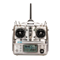
Power Indicator: When illuminated, indicates that there is power to the transmitter.
Power Switch: Turns the transmitter ON and OFF.
Select Key: Used to select Menu Programming Options.
Servo Reversing: Electronically switches the direction of servo travel, making it easy to change the direction that
the servo(s) operate.
Steering Trim Switch: Used to adjust the center trim of the steering servo.
Steering Wheel: Proportionally operates the model's right and left steering control. The steering wheel features a
molded grip for increased comfort, control and feel.
Temperature Range: The range in temperature of the outside air that the transmitter can safely and reliably
operate in.
Throttle Trigger: Controls the speed of the model, both forward and backward, or the model's brake.
Throttle Trim Switch: Used to adjust the center trim of the throttle servo.
Voltage Indicator: Displays the current voltage of the transmitter batteries. When the transmitter batteries reach
8.5 volts, LOW will be displayed and an audible alarm will sound.
Z-Connector: The type of servo and battery connector used by Airtronics. The Z-Connector is a universal connector
which is electronically compatible with the airborne components of other radio control system manufacturers.
Symbols
2.4GHz Frequency Band, Precautions 3
A
Antenna Wire, Receiver - Orientation of 8
Antenna Wire, Receiver - Denition of 7, 21
Antenna Wire, Receiver - Diagram of 6
Antenna, Transmitter - Denition of 7, 21
Antenna, Transmitter - Diagram of 6
Antenna, Transmitter - Orientation of 6
Anti-Lock Braking, Denition of 21
Anti-Lock Braking, Programming 16
Auxiliary Channel 3, Receiver Channel Slot - Diagram of 6
Auxiliary Channel 3 Switch, Denition of 7, 21
Auxiliary Channel 3 Switch, Diagram of 6
B
Batteries, Receiver - Installing 8
Batteries, Transmitter - Installing 8
Battery Compartment, Denition of 7, 21
Battery Compartment, Diagram of 6
Battery Options 9
Bind Button, Denition of 7, 21
Bind Button, Receiver - Diagram of 6
Bind Button, Transmitter - Diagram of 6
Binding. Transmitter and Receiver Binding
Binding, Denition of 21
Bind LED, Receiver - Diagram of 6
C
Channel Number Display, Overview 10
Channel Select Key. Programming Keys, Overview
Channel Select Key, Denition of 7, 21
Channel Select Key, Diagram of 6
Charging Jack, Denition of 7, 21
Charging Jack, Diagram of 6
Customer Service Information 5
D
Decrease Key. Programming Keys, Overview
Digital Trim Memory, Denition of 21
Digital Trim Memory, Using 17
Dual Rate, Denition of 21
Dual Rate Keys, Diagram of 6
Dual Rate, Steering - Adjusting 18
Dual Rate, Throttle - Adjusting 19
E
Electronic Speed Control, Connections 8
End Point Adjustment, Denition of 21
End Point Adjustment, Programming 14
Exponential, Denition of 21
Exponential, Programming 15
F
Fail Safe, Denition of 21
Fail Safe, Programming 11
FHSS-2, Denition of 21
Flow Chart. Programming Flow Chart
G
Grip, Denition of 7, 21
Grip, Diagram of 6
I
Increase/Decrease Keys, Denition of 7
Increase/Decrease Keys, Diagram of 6
Increase Key. Programming Keys, Overview
Input Voltage, Receiver. Nominal Input Voltage, Receiver
L
LCD. Multi-Function LCD
Low Voltage Alarm, Overview 19
Low Voltage Alarm, Denition of 21
M
Menu Selections, Overview 10
Continued on Next Page
 Loading...