

A
Aaron BarrySep 12, 2025
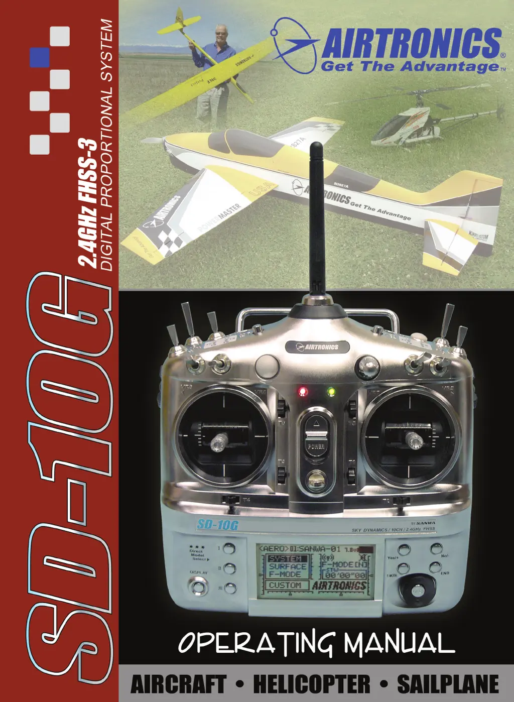
Why control surface trim changes when switching between Flight Modes on AIRTRONICS SD-10G Remote Control?
- Aamy66Sep 12, 2025
If the control surface trim changes when switching between Flight Modes on your AIRTRONICS Remote Control, it indicates that the Trim is set to SEP in the Trim Flight Mode menu. To resolve this, set the Trim to COM in the Trim Flight Mode menu.