Page 13
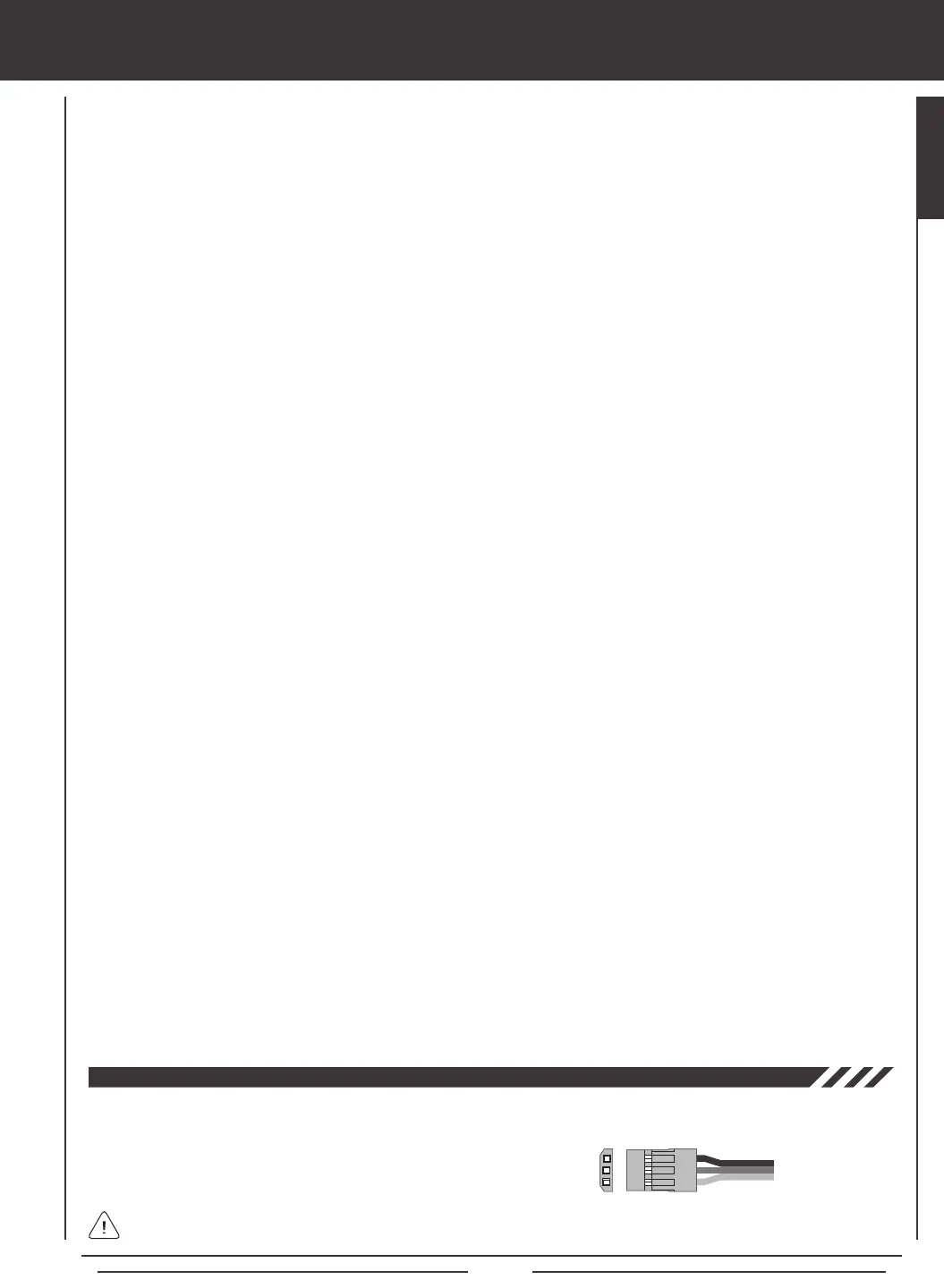
The 92104 10-Channel receiver included with your new SD-10G 2.4GHz FHSS-3 radio control system uses universal Airtronics
'Z' connectors which are electronically compatible with the servos of other radio control system manufacturers. The connectors
are rugged, but should be handled with care.
features familiarization
Coaxial Cables: The portion of each antenna wire that extends the Antenna Reception Wires. The Coaxial Cables can be bent
into gentle curves, however, do not bend the Coaxial Cables acutely, or repeatedly bend them, or the antenna wire's cores can
be damaged. For information on mounting the receiver and orientating the receiver antenna wires, see page 24.
DIN Connector: The DIN Connector is where the trainer cable (available separately) is plugged into. It is also used to plug the
Airtronics USB data cable (available separately) between the transmitter and your computer. An adapter to use the transmitter
with a ight simulator can also be plugged into the DIN Connector.
Direct Model Select Keys: The Direct Model Select Keys allow you to select one of three of your most-used models from
memory without going through the Model Select menu. For information on using the Direct Model Select Function, see page 31.
Display Key: Activates the transmitter's LCD Display without actually turning the transmitter ON. This allows you to check
and/or change programming settings without actually turning the transmitter ON. To turn only the LCD Display ON, press and
hold the DISPLAY Key for ~2 seconds. To turn the LCD Display OFF, press the DISPLAY Key once.
Flight Mode Key: Allows you to cycle through the ve different Flight Modes while in the Flight Mode Programming menu.
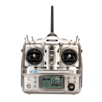
LCD Display: The heart of the programming and display features of the transmitter. All programming and transmitter display
functions are shown on the LCD Display. The Navigation Pad, the three Programming Keys, and the F-MODE Key to the right of
the LCD Display facilitate transmitter programming. The contrast of the LCD Display can be customized by the user to make it
easily readable in multiple lighting conditions.
Left-Hand Switch Array: The switches grouped on the left side of the transmitter are programmable and each will perform a
different function depending on what function is assigned to it. Each switch has a molded reference number next to it that
corresponds to the programming function in the Switch Assignment menu (the printed label corresponds to the two switches on
the front of the transmitter). Each of the ve switches is a three-position toggle switch except for the switch labeled 19/20/21
which is a spring-loaded switch.
Memory Expansion Card Slot: Holds the Memory Expansion Card (available separately). For information on installing the
Memory Expansion Card, see page 59.
Navigation Pad: The Navigation Pad is used in conjunction with the Programming Keys and the F-MODE Key to facilitate
transmitter programming. The Navigation Pad allows you to quickly and easily move the Programming Cursor up and down, and
right and left. The ENTER Key in the center of the Navigation Pad is used to open the selected menu or programming option.
Power Switch: Turns the transmitter ON and OFF.
Programming Keys: The Programming Keys are used in conjunction with the Navigation Pad and the F-MODE Key to facilitate
transmitter programming. The three Programming Keys consist of the YES/+ (Increase) Key, the NO/- (Decrease) Key, and the
END Key.
Push-Button Switch: Two Push-Button Switches are featured. Each Push-Button Switch is programmable and will perform a
different function depending on what function is assigned to it. For example, a Push-Button Switch can be programmed to control
the Stopwatch function.
RF Output Indicators: Both indicators illuminate when the transmitter is turned ON and transmitting a signal. If one or both of
the RF Output Indicators fails to illuminate, RF output is limited or non-existent. In this case, you should not y.
Right-Hand Switch Array: The switches grouped on the right side of the transmitter are programmable and each will perform
a different function depending on what function is assigned to it. Each switch has a molded reference number next to it that
corresponds to the programming function in the Switch Assignment menu (the printed label corresponds to the two switches on
the front of the transmitter). Each of the four switches is a three-position switch.
Throttle/Rudder Control Stick: Controls the Throttle and Rudder axes in the default Mode 2 conguration. For information on
changing transmitter modes, see page 41.
Trim Switch: Six separate Trim Switches (T 1, T 2, T 3, T 4, T 5, and T 6) are featured. Each Trim Switch will control a different
trim axis depending on which Model Type is selected.
- = Negative (Black)
+ = Positive (Red)
S = Signal (Blue)
When unplugging the servo connectors, it's best not to pull on the servo wire itself. This could result in damage to the servo
wire pins in the plastic plug.
GENERAL


 To Next Page