Page 147
glid Flight Mode menu
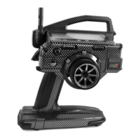
As you change the Point and Rate percentage values, you can use the graph and I/O numbers to visualize the ratio
between control stick movement and Camber or Reex travel throughout the entire deection range.
RATE setting range is -150% to 150%. POINT 1, 5, and 9 default Rate percentage values are 0%. The direction of Camber
or Reex travel in relation to elevator travel can be changed by programming positive or negative Rate percentage values.
3) Press the Navigation Pad
6
to highlight RATE>0%.
4) Press the YES/+ or NO/- keys to set the desired Rate percentage value.
When you change the Rate percentage value for Points 2, 3, 4, 6, 7, and 8, INH will be displayed. When you press the
YES/+ or NO/- keys, INH will change to 0%.
When you program the mix Curve so that the line is straight, this results in a Linear Curve. For example, if you set
the Point 1 percentage value to -50% and the Point 9 percentage value to 50%, Camber or Reex travel will be half the
amount that the elevator travels in both directions for the entire range of deection. If you wanted only Camber travel with up
elevator travel, you can set the Point 1 percentage value to 50%, and the Point 5 and Point 9 percentage values to 0%.
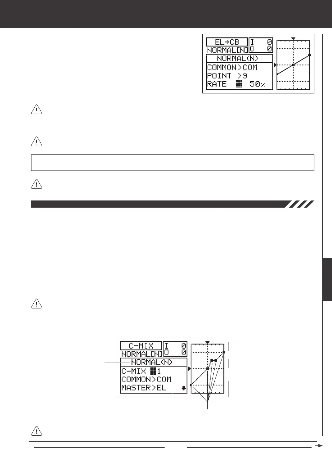
In all cases, the Master channel always controls the Slave channel. In the default conguration, all Compensation Mixes
can be programmed to be Linear, or precise channel Curves can be created by programming up to nine Points along
the Curve.
Transmitter F-MODE
Programming F-MODE
Stick Input (I)
Function Output (O)
150%
100%
100%
150%
0%
Point Positions
Transmitter F-MODE refers to the Flight Mode that the transmitter is currently operating in. Programming F-MODE refers
to the Flight Mode that you would like to change the programming for.
The C-Mix function allows you to program custom mixes that can control any number of desired functions in different combinations.
It is used to create your own custom mix if one of the pre-programmed mixes is not suitable. For example, you can create a
custom mix that mixes Camber to rudder, that can be used to help eliminate the need to use elevator during some turns, allowing
you to y with only the rudder control stick.
Like with pre-programmed mixes, Compensation Mixes are composed of a Master channel and a Slave channel. The Master
channel always controls the Slave channel. Any of the available ten channels can be programmed as a Master or a Slave. The
same channel can even be programmed as both a Master and a Slave. The C-Mix function includes nine custom-programmable
Points to ensure an extremely precise channel Curve to suit any situation. You can also program a Delay for the Slave function
that works independently (or with) the dedicated Channel Delay function described on page 86.
Up to ve C-Mix functions can be programmed separately for each of the ve Flight Modes or you can use the same C-Mix
programming across all ve Flight Modes. An Input and Output display, along with a graph, help with programming visualization.
GLID
 Loading...