Page 190
The VR Assign function allows you to reassign the High Pitch Trim and the Low Pitch Trim, and/or assign the auxiliary channels
to either of the two Auxiliary Levers (VR5 or VR6) or the Auxiliary Dial Knob (VR7). For example, you could use the Auxiliary
Dial Knob (VR7) to control your glow-powered helicopter's engine throttle mixture remotely. You can choose to program
VR Assignments separately for each of the ve Flight Modes or you can use the same VR Assignments programming across all
ve Flight Modes.
Transmitter F-MODE
Programming F-MODE
Transmitter F-MODE refers to the Flight Mode that the transmitter is currently operating in. Programming F-MODE refers
to the Flight Mode that you would like to change the programming for.
Choosing the Flight Mode - Common or Separate
When set to COM (Common), the VR ASSIGN settings will be the same regardless of which Flight Mode the transmitter is operating
in. You cannot program VR ASSIGN settings separately for each Flight Mode. When set to SEP (Separate), you can program
different VR ASSIGN settings separately for each Flight Mode.
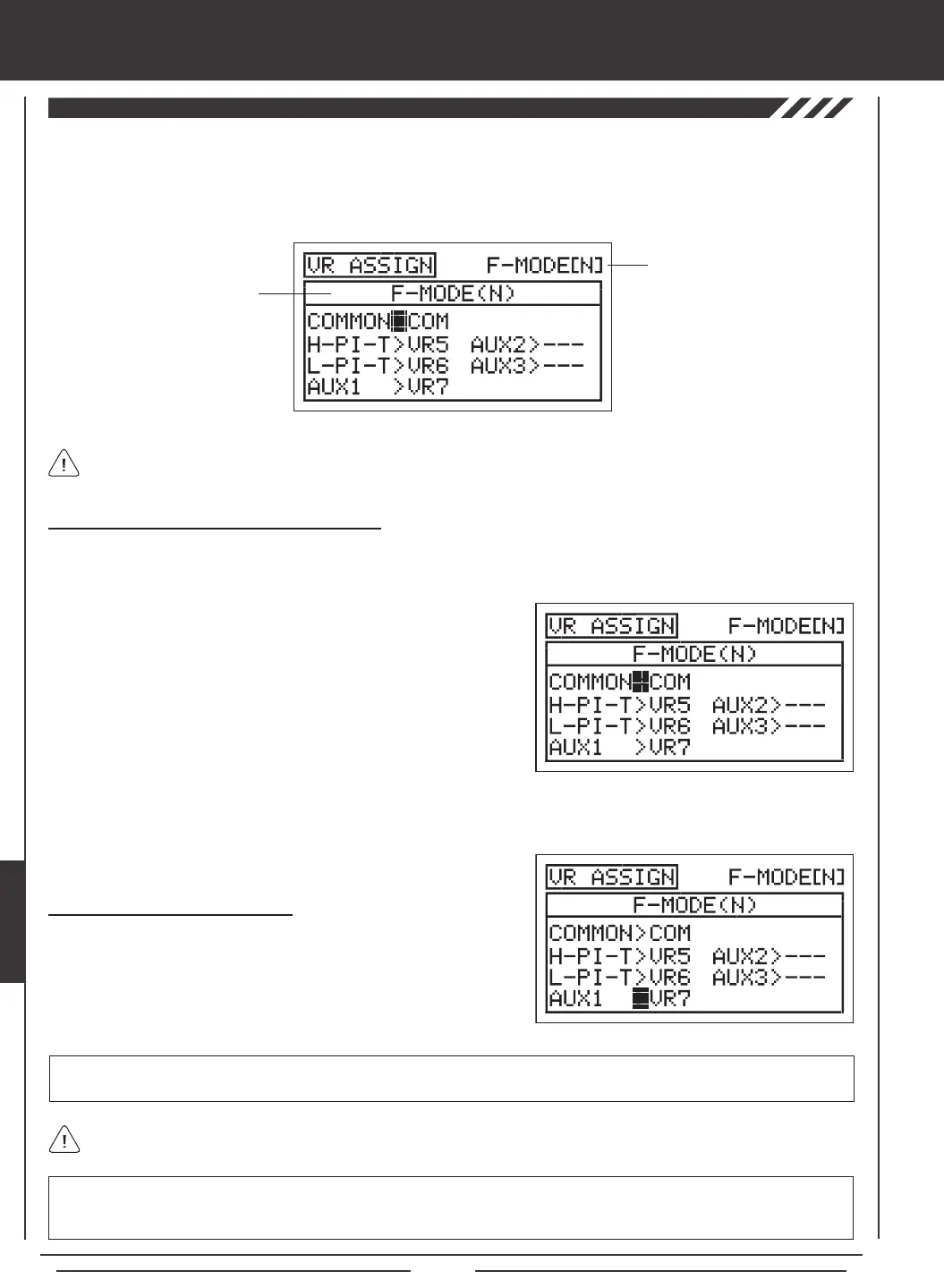
3) Press the F-MODE key to choose the F-MODE number you would like to program the VR Assignments for. Choose from
N, 1, 2, 3, or 4. The NORMAL (N) display will change, indicating which Flight Mode you are programming the VR Assignments for.
1) Press the Navigation Pad
56
to highlight VR ASSIGN, then press the
ENTER key to display the VR ASSIGN menu. The cursor will default to
COMMON>COM.
2) Press the YES/+ or NO/- keys to choose either COM or SEP. If set to
COM, skip to the Choosing Channel VR Assignments section. If set
to SEP, see step 3 below.
IMPORTANT Both sides of each auxiliary channel (High and Low), can be assigned to a Switch Position Number, using the
SW ASSIGN menu. If an auxiliary channel is assigned to both a switch and an Auxiliary Lever or the Auxiliary Dial Knob, the
switch takes precedence over the Auxiliary Lever or the Auxiliary Dial Knob in all cases.
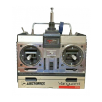
Choosing Channel VR Assignments
1) Press the Navigation Pad
5634
to highlight the channel you would
like to change the VR Assignment for, then press the YES/+ or NO/- keys
to change the VR Assignment.
VR ASSIGN setting range is ---, VR5, VR6, and VR7. The default setting for H-PI-T is VR5. The default setting for L-PI-T is VR6,
and the default setting for AUX1 is VR7. The default settings for MOTOR, AUX2 and AUX3 is ---.
To disable an Auxiliary Lever or the Auxiliary Dial Knob, assign --- to the desired channel. For example, if you don't want
Auxiliary Lever (VR6) to control Low Pitch Trim, change L-PI-T>VR6 to L-PI-T>
---
.
heli Flight Mode menu