Page 45
2) Press the Navigation Pad
5634
to move the cursor to the channel
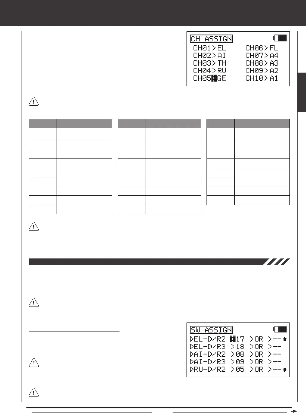
number you would like to change the Control function of, for example,
CH05>GE.
3) Press the YES/+ or NO/- keys to change the Control function associated
with the highlighted channel number. The Control function that you
choose will now be controlled by that receiver channel.
4) Repeat the same procedures to change the Control function for the
desired remaining channels.
SYSTEM MENU
LOF
ROF
LIF
RIF
GY
PI
GV
A1~A4
A description of each of the available Control functions is shown in the table below. Not all Control functions will be
available to change. Control functions displayed in the CH ASSIGN menu will vary based on the Model Type and Model
Type selection options you have programmed.
EL
AI
TH
RU
GE
FL
EL2
LA
RA
LT
RT
LOA
ROA
LIA
RIA
LF
RF
MT
ABBR. FUNCTION
Elevator
Aileron
Throttle
Rudder
Gear
Flap
Elevator 2
Left Aileron
Right Aileron
ABBR. FUNCTION
Left Throttle
Right Throttle
Left Outside Aileron
Right Outside Aileron
Left Inside Aileron
Right Inside Aileron
Left Flap
Right Flap
Motor
ABBR. FUNCTION
Left Outside Flap
Right Outside Flap
Left Inside Flap
Right Inside Flap
Gyro
Pitch
Governor
AUX1~AUX4
The channel numbers in the CH ASSIGN menu correspond to the receiver channel slot numbers. When you plug your
servos into the receiver, plug them into the channel slot numbers using the CH ASSIGN menu as a guide. The Surface
menu will indicate which servos to plug into which channel slots in the receiver, too. For example, if you set up an AERO model
with 2 aileron servos and dual elevator servos, the Surface menu will show exactly which channel slots in the receiver to plug
each of the servos into. For more information, see page 63.
The Switch Assignment function allows you to assign a function, such as Gear, Dual Rate, F-Mode, Snap Roll, Stopwatch,
etc, to any of the 9 three-position switches and the 2 push-button switches (31 positions total). Switches can be programmed
to operate in the standard fashion, or they can be made to operate interdependently using the Boolean conditions OR/AND.
Switches can also be programmed to always be ON.
The Switch Assignment functions and the default Switch Position Numbers displayed will vary depending on the Model
Type you have chosen. For a complete list of the default Switch Assignments, including the different Switch Assignment
functions available, see the tables on page 47.
The control sticks can also be programmed to function as switches
(Stick Switches) and those switches can be assigned to a function.
For more information, see page 48.
Changing or Adding Switch Assignments
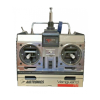
1) Press the Navigation Pad
56
to highlight SW ASSIGN, then press
the ENTER key to display the SW ASSIGN menu. The cursor will
default to EL-D/R2>17.
You can assign multiple functions to one switch by assigning the same Switch Position Number for each function. For
example, you could assign Elevator Dual Rate 2, Aileron Dual Rate 2, and Rudder Dual Rate 2 on one switch so that all
three Dual Rate functions can be changed at once.
SYSTEM