Page 91
aero Flight Mode Menu
The Trim Authority function allows you to control the ap channel using one of the Auxiliary Levers (VR5 or VR6) or the Auxiliary
Dial (VR7) when the ap switch is in Flap Position 1. In the default conguration, this function is assigned to Auxiliary Lever (VR6).
This allows you not only to have the option of using the three-position ap switch to control the aps, but also the option of using
an auxiliary lever to variably control the aps. You can choose to program Trim Authority values separately for each of the ve
Flight Modes or you can use the same Trim Authority programming values across all ve Flight Modes.
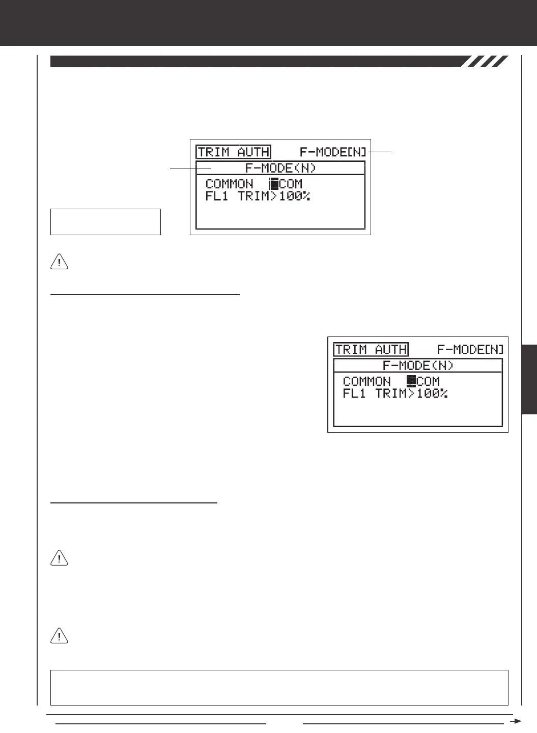
Transmitter F-MODE
Programming F-MODE
Transmitter F-MODE refers to the Flight Mode that the transmitter is currently operating in. Programming F-MODE refers
to the Flight Mode that you would like to change the programming for.
Choosing the Flight Mode - Common or Separate
When set to COM (Common), the TRIM AUTH settings will be the same regardless of which Flight Mode the transmitter is operating
in. You cannot program TRIM AUTH settings separately for each Flight Mode. When set to SEP (Separate), you can program
different TRIM AUTH settings separately for each Flight Mode.
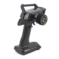
3) Press the F-MODE key to choose the F-MODE number you would like to program the Trim Authority function for. Choose from
N, 1, 2, 3, or 4. The F-MODE (N) display will change, indicating which Flight Mode you are programming the Trim Authority
function for.
1) Press the Navigation Pad
56
to highlight TRIM AUTH, then press the
ENTER key to display the TRIM AUTH menu. The cursor will default to
COMMON>COM.
2) Press the YES/+ or NO/- keys to choose either COM or SEP. If set to
COM, skip to the Changing the Flap 1 Trim Percentage Value section.
If set to SEP, see step 3 below.
Changing the Flap 1 Trim Percentage Value
In the default conguration, the aps are programmed to a three-position switch. When the switch is in Flap Position N, the aps
are full up. When the switch is in Flap Position 1, the aps are 50% down [with Auxiliary Lever (VR6) centered], and when the
switch is in Flap Position 2, the aps are 100% down. This can be seen by looking at the FL (Flap) channel in the Surface menu.
Auxiliary Lever (VR6)
Flap 1 Trim
When the Flap 1 Trim Authority percentage value is set to 100%, Auxiliary Lever (VR6) will control the aps variably from 0%
to 100% travel. When the Flap 1 Trim Authority percentage value is set to 0%, Auxiliary Lever (VR6) is Inhibited and will NOT
control the aps at all. When the Flap 1 Trim Authority percentage value is set anywhere between the 0% and 100%, the ap's
center position will be lowered and the overall travel when Auxiliary Lever (VR6) is used to control the aps will be decreased.
Auxiliary lever VR6 will variably control the ap channel ONLY when the ap switch is in Flap Position 1.
If the Flap 1 Trim Authority percentage value is set lower than 100%, the center position of the aps will be lowered when
the ap switch is in Flap Position 1. In this situation, to raise the aps completely, the ap switch must be moved to Flap
Position N.
IMPORTANT Auxiliary lever VR6 cannot control the ap servo movement more than 100% travel. If your Flap Position 2 End
Point Adjustment is set to a percentage value greater than 100%, you will need to move the ap switch to Flap Position 2 to
lower the aps beyond the 100% that is controlled by Auxiliary Lever (VR6) while the aps are in Flap Position 1.
AERO