Page 92
The Cross-Trim function allows you to electronically swap trim switch functions. Some pilots prefer this over the standard
arrangement in which the trim switches adjacent to the control sticks control the trim for that control function. For example, in the
default conguration, the throttle trim switch will control the throttle trim and the elevator trim switch will control the elevator trim.
With TH
34
EL Cross-Trim Activated, the throttle trim switch will control the elevator trim and the elevator trim switch will control
the throttle trim. You can choose to program Cross-Trim separately for each of the ve Flight Modes or you can use the same
Cross-Trim programming across all ve Flight Modes.
aero Flight Mode menu
Transmitter F-MODE
Programming F-MODE
Transmitter F-MODE refers to the Flight Mode that the transmitter is currently operating in. Programming F-MODE refers
to the Flight Mode that you would like to change the programming for.
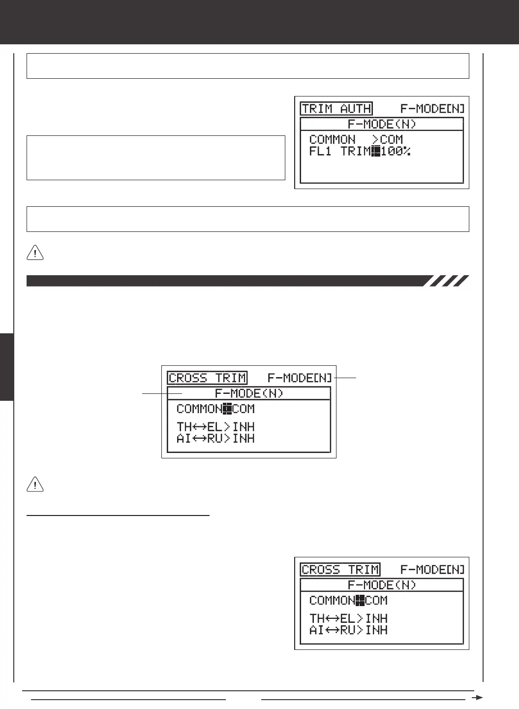
Choosing the Flight Mode - Common or Separate
When set to COM (Common), the CROSS-TRIM settings will be the same regardless of which Flight Mode the transmitter is
operating in. You cannot program CROSS-TRIM settings separately for each Flight Mode. When set to SEP (Separate), you can
program different CROSS-TRIM settings separately for each Flight Mode.
3) Press the F-MODE key to choose the F-MODE number you would like to program the Cross-Trim function for. Choose from N, 1,
2, 3, or 4. The F-MODE (N) display will change, indicating which Flight Mode you are programming the Cross-Trim function for.
1) Press the Navigation Pad
56
to highlight CROSS-TRIM, then press
the ENTER key to display the CROSS-TRIM menu. The cursor will
default to COMMON>COM.
2) Press the YES/+ or NO/- keys to choose either COM or SEP. If set to
COM, skip to the Changing the Throttle/Elevator Cross-Trim section. If
set to SEP, see step 3 below.
FL 1 TRIM setting range is 0% to 100%. The default setting is 100%.
Decreasing the FL 1 TRIM percentage value lowers the ap center
position and decreases the overall travel when Auxiliary Lever (VR6) is
used to control the aps.
1) Press the Navigation Pad
6
to highlight FL1 TRIM>100%, then press
the YES/+ or NO/- keys to change the FL1 TRIM percentage value.
IMPORTANT In the default conguration, Auxiliary Lever (VR6) variably controls the ap channel when the ap switch is in Flap
Position 1. Prior to setting your ap End Point Adjustments in the Surface menu, make sure that Auxiliary Lever (VR6) is centered.
IMPORTANT When the ap switch is moved to Flap Position 1, the aps will move to the position where Auxiliary Lever
(VR6) was last left in.
The Trim Authority Flap 1 VR Auxiliary Lever Override function can be turned OFF by changing the FLAP1>VR6 setting in
the VR ASSIGN menu. For more information, see page 108.
 Loading...