Page 64
Locking and Unlocking Surface Menu Adjustment Options
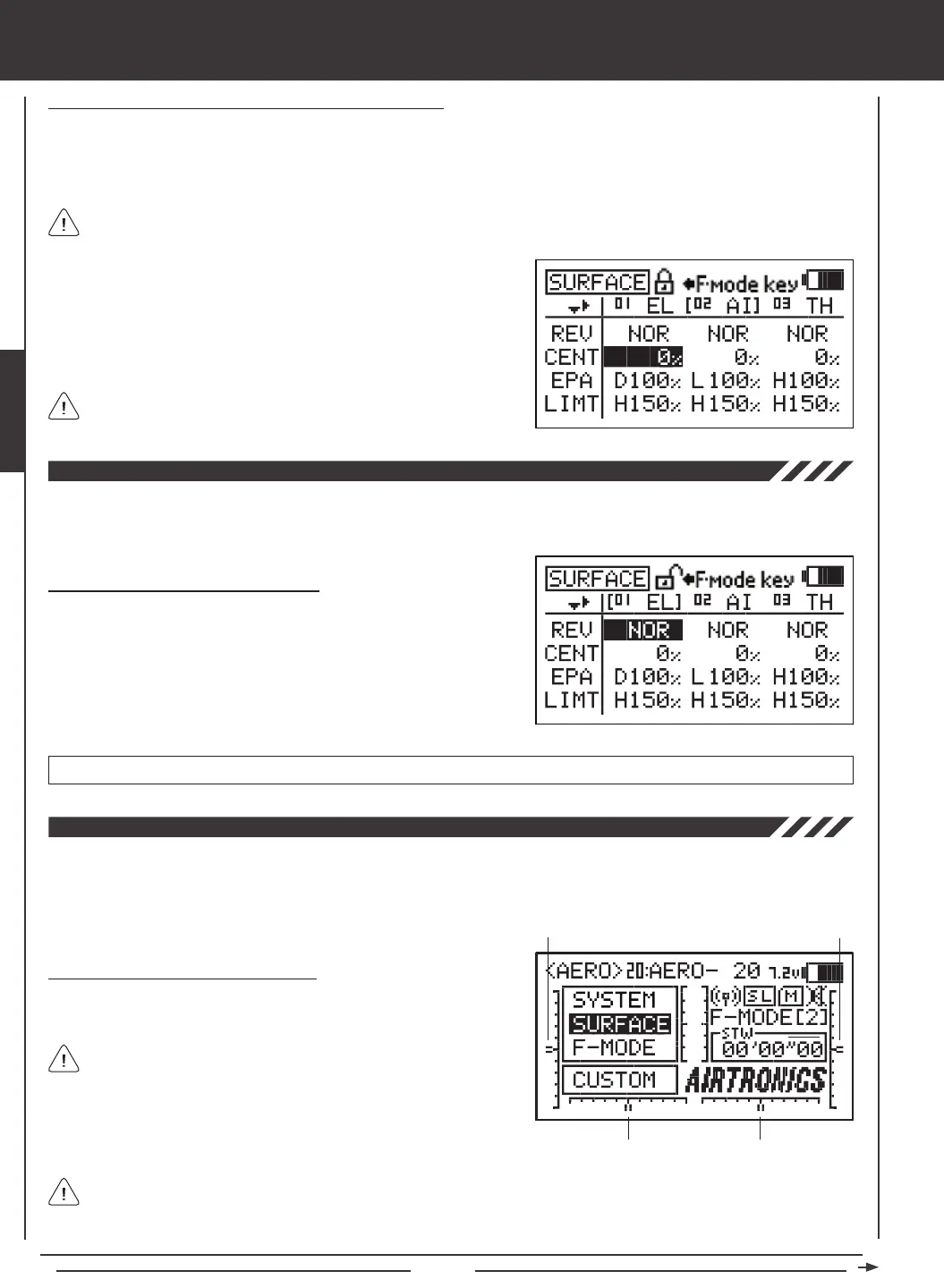
Individual Adjustment Options (REV, CENT, etc.), can be Locked to prevent unwanted or accidental changes to those specic
Adjustment Values. The current Locked/Unlocked state of each of the Adjustment Options is indicated by the padlock icon at
the top of the Surface menu. When the padlock is Open (Unlocked), Adjustment Values for that specic Adjustment Option can
be changed. When the padlock is Closed (Locked), Adjustment Values for that specic Adjustment Option cannot be changed.
1) Press the Navigation Pad
56
to highlight an Adjustment Value
adjacent to the Adjustment Option you would like to Lock. For example,
to Lock the CENT Adjustment Option, highlight the Adjustment Value
adjacent to CENT, then press the F-MODE key.
2) To Unlock the Adjustment Option, press the F-MODE key a second time.
In the default conguration, all Adjustment Options are Unlocked.
surface MENU
Individual Adjustment Options can be Locked or Unlocked separately. For example, you can Lock REV Adjustment
Options, but leave EPA Adjustment Options Unlocked.
The Reversing function electronically switches the direction of servo travel. For example, if you pull the elevator control stick
back for Up elevator, but your elevator moves Down, you can use the Reversing function to switch the direction of servo travel
to make the elevator move Up.
Changing Reversing Adjustment Values
1) Press the Navigation Pad
34
to highlight the REV Adjustment Value
for the channel that you would like to change.
2) Press the YES/+ or NO/- keys to change the REV Adjustment Value
to set the direction of servo travel, then change the desired remaining
REV Adjustment Values using the same techniques.
REV setting range is NOR/REV. The default setting is NOR.
The Centering function allows you to ne-tune the Center (Neutral) position of each servo. It's not unusual that when you install
the servo horn onto your servo that the servo horn is not perfectly centered. Centering allows you to center the servo horn perfectly.
Centering also makes it possible to keep the trim switches centered while ensuring that the servo horns remain centered. For
more information, see the Zeroing Out Trim section on the next page.
Changing Centering Adjustment Values
1) Before changing the CENT Adjustment Values, be sure to set the trim
switches to the center positions as displayed on the Top menu.
An audible tone is heard when the trim switches reach the center
position. This allows you to know when the trim switches reach the
center position without the need to look at the Trim Indicators on the
Top menu.
Trim 3
Trim 4
Trim 1
Trim 2
The SD-10G transmitter features Digital Trim Memory. Any amount of trim that you set during ight, using either the
trim switches or the YES/+ and NO/- keys from within the Trim menu, is automatically stored in memory for that specic
channel and model, and for that specic Flight Mode (if enabled). The Trim percentage values for each model will automatically
be loaded when the transmitter is turned ON and your model is selected. For more information, see page 89.
 Loading...