ENGLISH
1. WARNINGS AND ENVIRONMENTAL POLICY................................................................55
1.1. Warnings ..................................................................................................................55
1.2. Environmental Policy .................................................................................................55
2. SYSTEM DESCRIPTION...................................................................................................56
3. SYSTEM COMPONENTS..................................................................................................56
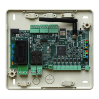
3.1. Flexa System Control Unit .........................................................................................56
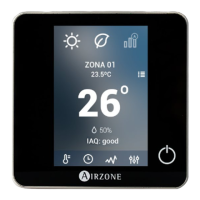
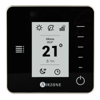
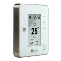
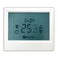
3.2. User’s Interfaces........................................................................................................56
3.3. HVAC Communication Gateway and Measuring Kit..................................................56
3.4. Airzone Mechanical Components ..............................................................................57
3.4.1. Deflector............................................................................................................57
3.4.2. Security Damper................................................................................................57
3.4.3. Bypass Damper.................................................................................................57
4. INSTALLATION: ASSEMBLY AND CONNECTION.........................................................57
4.1. Assembly and Connection of Flexa System Control Unit...........................................57
4.2. Assembly and Connection of User’s Interfaces .........................................................58
4.3. Assembly and Connection of HVAC Communication Gateway and Measuring Kit....58
4.3.1. HVAC Communication Gateway and Measuring Kit..........................................58
4.3.2. EnerFace...........................................................................................................58
4.4. Deflector, Security and Bypass Damper Assembly....................................................59
5. START-UP.........................................................................................................................59
5.1. System Control Unit Start-up .....................................................................................59
5.2. BlueFace/ EnerFace Start-up ....................................................................................59
5.3. Tacto Flexa Thermostat Start-up ...............................................................................60
6. INSTALLATION PARAMETERS SETUP..........................................................................61
6.1. BlueFace and EnerFace Setup..................................................................................61
6.2. Tacto Flexa Thermostat Setup...................................................................................61
6.2.1. Setup Parameters Description...........................................................................62
7. CONNECTION TO AC UNITS ...........................................................................................64
7.1. Stop/Start Connection................................................................................................64
7.2. Infrared Connection (IR) ............................................................................................64
7.3. HVAC Communication Gateway Connection.............................................................64
8. EXCEPTION CODES.........................................................................................................65
9. SELF-TESTING PROCESS...............................................................................................66
APPENDIX 1: FLEXA TACTO THERMOSTAT ASSEMBLY................................................67
APPENDIX 2: BATTERY SAVING MODE ............................................................................67
APPENDIX 3: MAIN CONTROLLER AND ZONE THERMOSTAT RESET ..........................68