6
A-MIP 210 V1.06
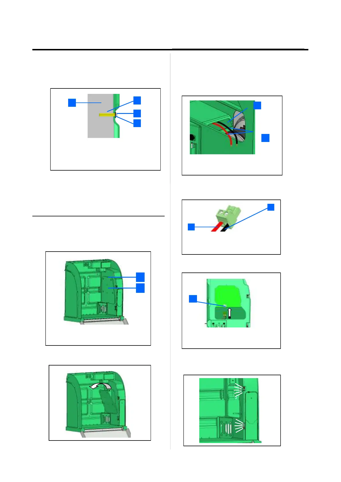
Installation
• Fixing must be adapted to the type of support the Aivia
is being fixed on.
• Aivia fixing must be able to carry a minimal load of 20
kg.
• Fixing example:
• Shim plus screw head thickness must not exceed
8mm.
slide all the necessary cables through the hole
before fixing the Aivia to the wall.
Affix the Aivia using the 3 fixing holes..
1
2
3
4
1 Supporting wall.
2 Pin/Nylon plug.
3 Fixing screw, M6 minimum, M8 maximum.
4 Shim 14mm maximum.
Connect the power supply to the Aivia
• The Aivia must be powered using 24V DC, see the
« Power supply » section
• Slide the power supply cables through the cable
passage.
• Connect the cables on the connector block respecting
the polarity.
1 Cable passage
2 Power supply cables (24V)
2
1
2
1
1 +24V DC Red cable.
2 0V Black cable.
1
1 Board power supply connector
• Plug the connector block on the board.
• Check the energization of the Aivia by verifying that the
white indicators are lighted.
Connect power to the Aivia
The Aivia must be supplied with 24VDC power,
ensure compliance with the "Electrical Installation"
section
•
Unscrew the door mounting screw with a star
screwdriver and tip the door from above.
1
2
1
2
Access door mounting screws.
Electronics access door