Ill.
DESCRIPTION
OF
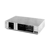
GX-F51
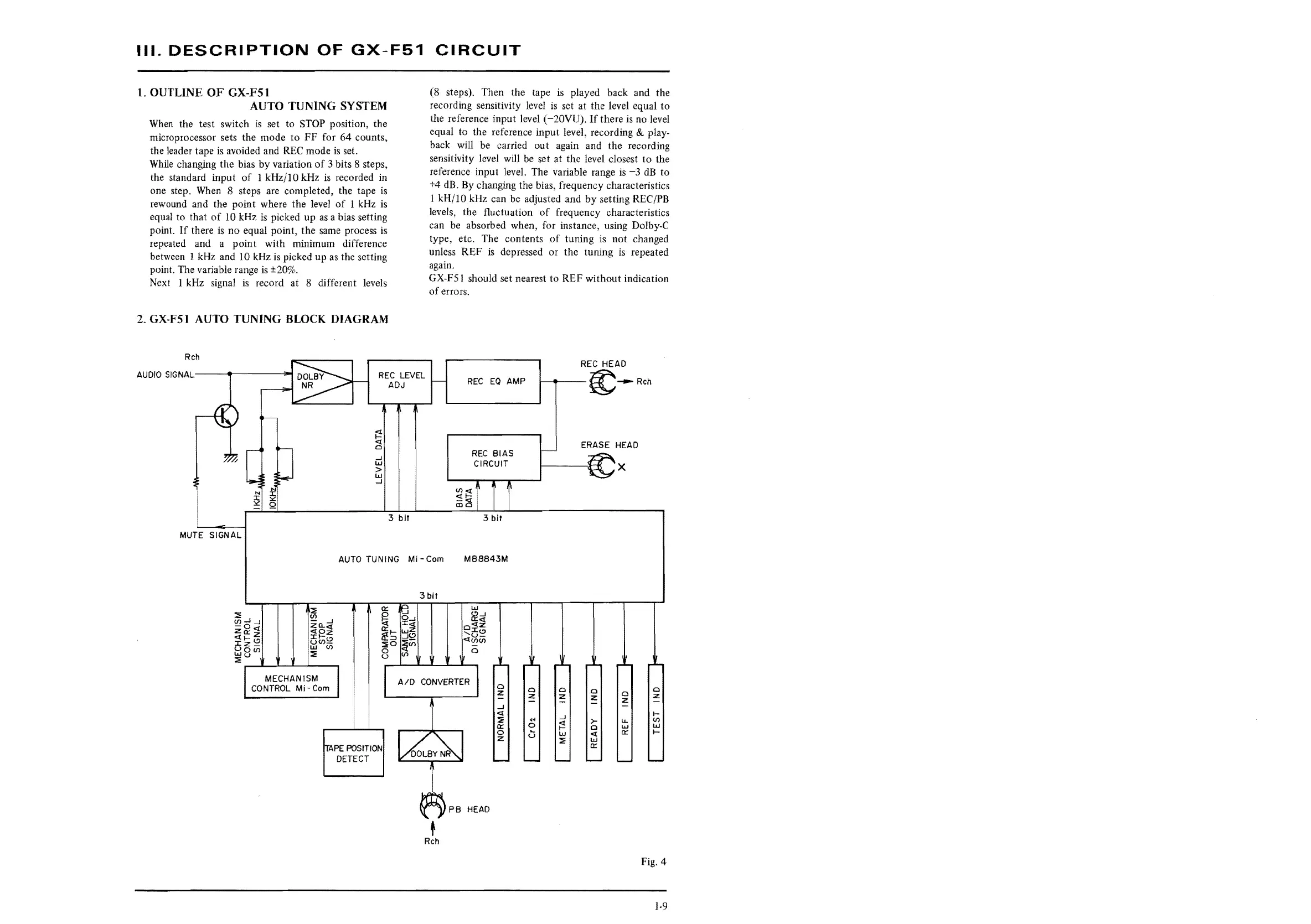
1.
OUTLINE
OF
GX-FS
1
AUTO
TUNING
SYSTEM
When
the test switch
is
set to
STOP
position, the
microprocessor sets the mode
to
FF
for 64 counts,
the leader tape
is
avoided and
REC
mode
is
set.
While
changing the bias by variation
of
3 bits 8 steps,
the standard input
of
l kHz/IO kHz
is
recorded in
one step. When
8 steps are completed, the tape
is
rewound and the point where the level
of
1 kHz
is
equal to that
of
IO
kHz
is
picked up
as
a bias setting
point.
If
there
is
no equal point, the same process
is
repeated and a point with minimum difference
between
1 kHz and
10
kHz
is
picked up
as
the setting
point. The variable range
is
±20%.
Next I kHz signal
is
record at 8 different levels
2.
GX-FSl
AUTO
TUNING
BLOCK
DIAGRAM
Reh
AUDIO
SIGNAL-------=-1
REC
LEVEL
ADJ
MUTE SIGNAL
N N
2 2
Q
j::
c3
..J
w
>
w
_J
3
bit
CIRCUIT
(8 steps). Then the tape
is
played back and the
recording sensitivity level
is
set at
the
level equal
to
the reference input level (-20VU).
If
there
is
no level
equal to the reference input level, recording
& play-
back will be carried out again and the recording
sensitivity level will
be
set at the level closest
to
the
reference input level. The variable range
is
-3
dB
to
+4 dB. By changing the bias, frequency characteristics
I kH/10 kHz can be adjusted and
by
setting
REC/PB
levels, the fluctuation
of
frequency characteristics
can
be
absorbed when, for instance, using Dolby-C
type, etc. The contents
of
tuning
is
not changed
unless
REF
is
depressed or the tuning
is
repeated
again.
GX-F51
should set nearest to REF without indication
of
errors.
REC
EO
AMP
REC
BIAS
CIRCUIT
REC
HEAD
1------~--
Reh
ERASE
HEAD
--~x
..._-
..... --.--,...--....1
3
bit
AUTO
TUNING Ml
-Com
MB8843M
::ii:
Cf)
za..
..J
<CO<C
:t:F-z
<.,)Cf)~
w Cf)
~
MECHANISM
CONTROL
Mi-Com
a::
~
a::,_
If
:::i
~o
0
u
~PE
POSITION
DETECT
c...l
0..J
:t::l!
~(!)
::ii:-
<r.(J)
(J)
AID
3
bit
w
(!)..J
Cl:<(
o<CZ
':C(!)
<CU-
I.I)(/)
0
~PB
HEAD
t
Reh
a
z
a
a
0
a
z
z
z
a
z
z
_J
<(
..J
I-
::ii
...
~
>-
LL
(J)
0::
0
a
w
IJ.J
0
u
IJ.J
<(
a::
I-
z
~
w
a::
Fig. 4
1-9
 Loading...