IV.
AUTO
FADER
CIRCUIT
FADE
OUT
...
..,
a::
1-,s-J
~
Cl4
"'
..,
TR4
a::
.;
0
j
"'
u
TR5
>
'°
r-::
+
~
>
cc
..J
0
0
~
L
__
J
PHI
L.........J.
___
.,_..._
____
+---~--..___.~+-------,._VGNO
ry1_-f55~-1
I I
I I
L
_____
J
FADE
OUT
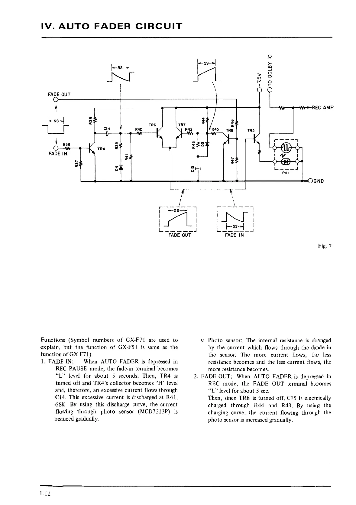
Functions (Symbol numbers
of
GX-F71 are used
to
explain,
but
the function
of
GX-FS
l
is
same
as
the
function
of
GX-F7 l ).
I.
FADE IN; When AUTO FADER
is
depressed in
\
.---.l.
-,
l~I
I I
I I
I
~5s-,,,
I
L
_____
.J
FADE
IN
Fig.
7
o Photo sensor; The internal resistance
is
clianged
by the current which flows through the diode
in
the sensor. The more current flows, the
less
resistance becomes and the
less
current flovs, the
more resistance becomes.
REC
PAUSE mode, the fade-in terminal becomes
"L"
level for about 5 seconds. Then, TR4
is
turned
off
and TR4's collector becomes
"H"
level
and, therefore, an excessive current flows through
CI
4.
This excessive current
is
discharged at R41,
68K.
By
using this discharge curve, the current
flowing through photo sensor (MCD72 l 3P)
is
reduced gradually.
2. FADE OUT; When AUTO FADER
is
depressed
in
REC mode, the FADE OUT terminal becomes
"L"
level for about 5 sec.
1-12
Then, since TR8
is
turned off, C
15
is
electrically
charged through R44 and R43.
By
using the
charging curve, the current flowing throu~h the
photo sensor
is
increased gradually.
 Loading...