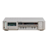
GX-F71
DIGITAL
VOLTMETER
DC
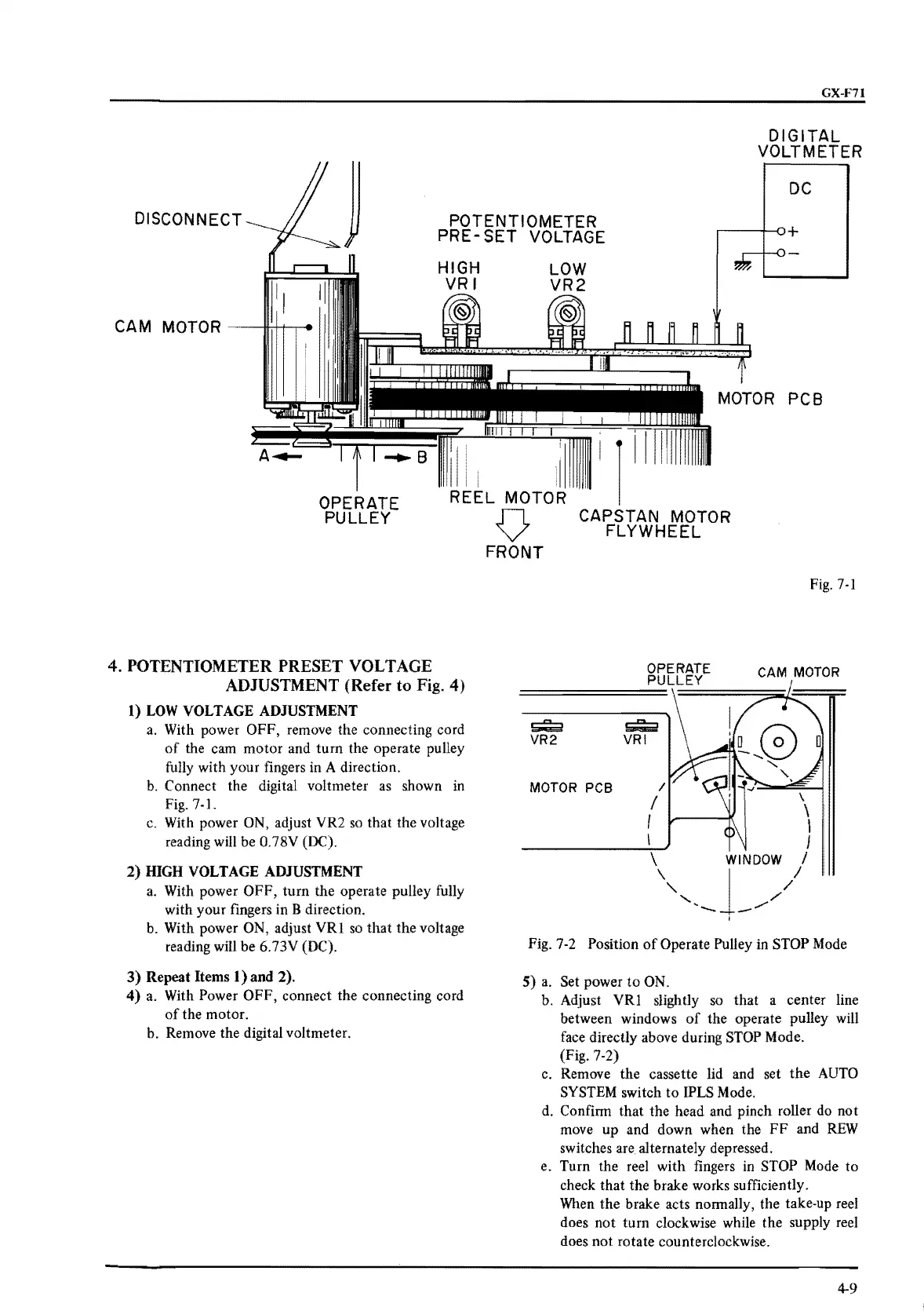
DISCONNECT
POTENTIOMETER
PRE-
SET
VOLTAGE
.---+--o+
PCB
i
OPERATE
PULLEY
REEL MOTOR
4.
POTENTIOMETER PRESET VOLTAGE
ADJUSTMENT (Refer
to
Fig.
4)
1)
LOW
VOLTAGE
ADJUSTMENT
a.
With power OFF, remove the connecting cord
of
the cam
motor
and
turn
the
operate pulley
fully with your fingers in A direction.
b.
Connect the digital voltmeter as shown in
Fig.
7-1.
c. With power ON, adjust VR2
so
that the voltage
reading
will
be 0.78V (OC).
2)
HIGH
VOLTAGE
ADJUSTMENT
a.
With power
OFF,
turn
the operate pulley fully
with your fingers in B direction.
b.
With power ON, adjust
VRI
so
that
the
voltage
reading will be 6.73V (OC).
3)
Repeat Items 1) and 2).
4) a. With Power
OFF,
connect the connecting cord
of
the motor.
b. Remove the digital voltmeter.
V
FRONT
CAPSTAN MOTOR
FLYWHEEL
OPERATE
PULLEY
Fig.
7-1
CAM
MOTOR
~
~
I
VR2
VRI
0
a
MOTOR PCB
I
\
I
\
I
I
I
I
\
WINDOW
I
\
J_
✓,,/
I
"
I
Fig. 7-2 Position
of
Operate Pulley in STOP Mode
S)
a.
Set power
to
ON.
b. Adjust
VRI
slightly so
that
a center line
between windows
of
the operate pulley will
face directly above during STOP Mode.
(Fig. 7-2)
c. Remove the cassette lid and set
the
AUTO
SYSTEM switch
to
IPLS Mode.
d. Confirm that the head and pinch roller do
not
move
up
and down when the
FF
and
REW
switches
are.
alternately depressed.
e. Turn the reel with fingers in STOP Mode to
check that the brake works sufficiently.
When the brake acts normally, the take-up reel
does
not
turn clockwise while the supply reel
does
not
rotate counterclockwise.
4-9
 Loading...