

B
Brooke YoungAug 4, 2025
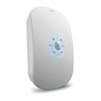
What happens if Akw Bathroom Fixtures experience instantaneous overtemperature?
- RRyan ShepardAug 5, 2025
If Akw Bathroom Fixtures experience instantaneous overtemperature, the shower will continue to operate, but the heating element and water outlet will be disabled. An error message will appear during operation. The system automatically resets once the overtemperature condition is resolved through natural cooling or by rinsing cold water through the shower heater.