4
The electronic video door entry system is a direct consequence
of the growing demand for increased measures of security in pre-
sent day housing projects. In addition to being able to listen to the
visitor, as offered by the existing electronic door entry systems on
the market, the visitor can also be identified visually affording gre-
ater control over access to the building.
The microprocessor-based technology that the ALCAD video
door entry system uses allows any installation configuration to be
carried out in the most reliable and comfortable manner.
Standard installations, such as video door entry installations in
buildings with a single point of entry, or more complex installa-
tions, such as installations in buildings with several points of entry
or on estates with one or more general access points are catered
for.
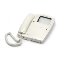
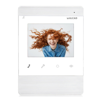
The main elements of a video door entry system are an entran-
ce panel, to be installed at the entry point of the building, and a
monitor in each house or flat.
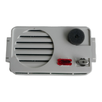
The entrance panel has a video unit and a series of pushbuttons.
The video unit is the element of the system which captures the
image of the person who is calling. The panel has auxiliary ligh-
ting in order to see the visitor, even in conditions of low external
light. In black and white systems this lighting is by means of infra
red leds (light emitting diodes).The light provided by these leds is
invisible to the human eye which means that visitors can be obser-
ved without them being aware of the fact. The pushbuttons of the
panel allows communication with the different houses or flats.
Each pushbutton corresponds to one house or flat so the number
of pushbuttons will correspond to the number of houses or flats in
the system. When a pushbutton is pressed, a call tone is genera-
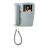
ted which sounds on the monitor of the corresponding house or
flat. The monitor comes on at the same time, showing the image of
the person who has called. Communication with the visitor is esta-
blished by simply picking up the handset of the monitor. The moni-
tor has a specific button to allow the visitor access to the property.
When this button is pressed the electric lock installed in the entry
door of the building allows the visitor to enter.
Just as in conventional TV installations, the video door entry
makes use of tap-offs and splitters to distribute the video signal of
the video unit. The tap-offs, normally located on each floor of the
building, allow the video signal to be split to the different monitors
of the installation. The splitters are used when several video
columns or risers are needed.
As any other electronic system, the video door entry system
requires an external power supply in order to work. This function
is carried out by the power supply units which provide the requi-
red voltages for the system from the mains supply. The power
supply units are usually located in a safe place in the hall of the
ground floor or in another common area of the building.
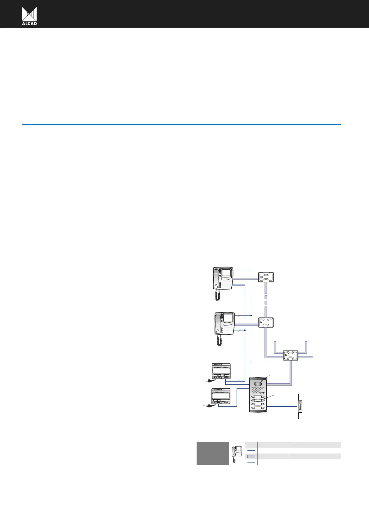
DESCRIPTION
ELECTRONIC VIDEO DOOR ENTRY SYSTEM
1
230 V
V
230 V
V
ELECTRIC LOCK
POWER SUPPLIES
SPLITTER
TAPP-OFF
MONITOR
T THE FLAT
ENTRANCE PANEL
PUSH BUTTON
VIDEO UNIT
6+N+COAXIAL SYSTEM
4 Commons + 1 call5
COAXIAL
Number of wires Description
Transmission of the video signal
Power supply of the monitor2
WIRES IN
EACH MONITOR
FIRST FLOOR
LAST FLOOR
230 V
230 V
5
2
COAXIAL
COAXIAL
2
4+N
An entrance panel can be placed on each access point in
installations in buildings with several entry points or on estates
with one or several general entry points and one or several
estate buildings. The control of the different access points is
carried out by the same entrance panels which make up the
video door entry system, which means that the different panels
of the installation must be interconnected.
The video door entry system described in this manual uses
a 6+N+coaxial connection system. The coaxial cable, the
means of transmission of the video signal captured by the
video unit, and two wires for the power supply of the monitors
of the installation, are added to the 4+N connections used by
the electronic door entry systems (4 common wires and 1 inde-
pendent call wire per house or flat). In this way, 7 wires (4
common wires + 1 call wire + 2 wires for the power supply of
the monitor) reach each monitor of the installation as well as
the coaxial cable carrying the video signal.
 Loading...