200 Series Tooling Alcoa Fastening Systems
11
S
S
ETTING
ETTING
AND
AND
C
C
HECKING
HECKING
S
S
HIFT
HIFT
V
V
ALVE
ALVE
U
U
SING
SING
S
S
HIFT
HIFT
S
S
ETTING
ETTING
K
K
IT
IT
P
P
REFERRED
REFERRED
M
M
ETHOD
ETHOD
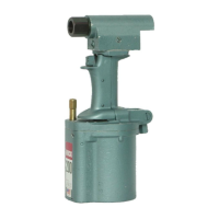
- KIT 107569 (F
- KIT 107569 (F
IG
IG
9)
9)
1. Use only a tool which has been prepared for use and
filled and bled per instructions in this manual.
2. A filtered-regulated-lubricated air supply capable of sup-
plying 18 CFM @ 90-100 psi must be available.
3. Screw Retaining Nut I 00530 (5-1) againist head (2-1).
4. Assemble Adapter 107564 through Skidmore-Wilhelm
Tester 107573 and engage threads of tool pull piston (2-
21). Tighten “finger tight.”
5. Screw Air Metering Fitting 101303 into air connector and
air supply hose. Set regulator for 90-I 00 psi.
6. Back out shift valve adjusting screw (4-30), keeping sur-
face of adjusting screw approximately 1/8” below sur-
face of cylinder. Use Wrench 100878.
7. Depress tool trigger (3-3 1) quickly and watch needle on
tester gage. Full spindle load will be shown. There will
not be a pause indicating shifting of the shift valve
because it is inoperative with adjusting screw backed
out. Release trigger. Do not hold down.
8. Select spindle load at shift from table 15 for Huck
Fastener to be installed.
9. Turin in adjusting screw until needle of gage pauses
before reaching full spindle load when trigger is
depressed. This is ‘‘Spindle Load at Shift.’’
10. Adjust screw to obtain desired “Spindle Load at Shift”
selected from table.
11. Trigger tool ten times to verify setting Note: The needle
will bounce slightly when shift occurs. Do not confuse
this bounce with the pause indicating shift.
12. Disconnect air supply and remove setting kit and
101303 Air Metering Fitting from tool.
13. Attach nose assembly per instructions on Nose
Assembly Data Sheet.
14. Install a few fasteners in a test plate of proper thickness
and with proper size holes to verify that shift valve has
been set properly and that nose assembly is functioning
properly.
A
A
LTERNATE
LTERNATE
M
M
ETHOD
ETHOD
- KIT101300 (F
- KIT101300 (F
IG
IG
10)
10)
1. Use only a tool which has been prepared for use and
filled and bled per instructions in this manual.
2. A filtered-regulated-lubricated air supply capable of sup-
plying 18 CFM@ 90-100 psi must be available.
3. Screw Stop Nut 101304 onto threads of pull piston (2-
21). Tighten “finger tight.”
4. Remove bleed plug (4-2) from side of cylinder (4-1) and
screw in Adapter 101302 with Gage 101301. Note: Be
sure there is an O-ring on the Adapter.
5. Screw Air Metering Fitting 101303 into air connector (3-
4).
6. Attach air supply hose to tool. Set regulator for 90-100
psi.
7. Back out shift valve adjusting screw (4-30) flush with
bottom of cylinder (4-1). Use Wrench 100878.
8. Depress tool trigger (3-31) quickly and watch needle on
Gage 101301. Full spindle load will be shown. There will
not be a pause indicating shifting of time shift valve
because it is inoperative with adjusting screw backed
out. Release trigger — do not hold down.
9. Select hydraulic pressure at shift from table 15 for Huck
Fastener to be installed.
10. Turn in adjusting screw until needle of gage pauses
before reaching full spindle load when trigger is
depressed. This is “Hydraulic Pressure at Shift.”
11. Adjust screw to obtain desired hydraulic pressure at shift
selected from the table.
12. Trigger tool ten times to verify setting. Note: The needle
will bounce slightly when shift occurs. Do not confuse
this bounce with the pause indicating shift.
13. Disconnect air supply and remove setting kit including
Air Metering Fitting 101303.
14. Attach nose assembly per instructions on Nose
Assembly Data Sheet.
15. Install a few fasteners in a test plate of proper thickness
and with proper size holes to verify that shift valve has
been set properly and that nose assembly is functioning
properly.