200 Series Tooling Alcoa Fastening Systems
8
(See Good Services Practices.)
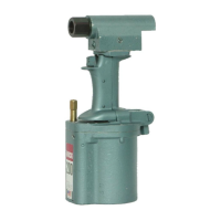
The Model 200 Huck Installation Tool is shipped with
a plastic plug in the swivel air inlet connector (3-4).
This connector has 1/4-18 female pipe threads to
accept the hose fittings. Quick disconnect fittings and
3/8 inside diameter air hose are recommended. (Air
hose and quick disconnect fittings are not available
from Huck.)
An air filter-regulator-lubricator is also recommended.
An air supply of 90-100 psi capable of 18 CFM must
be available. (Based on 30 tool cycles per minute).
The air connector bolt (3-5) has an air relief valve
built in to exhaust air at 100-110 psi.
1. Remove plastic plug from air inlet connector and
pour in a small quantity of Automatic Transmission
Fluid. Assemble the hose fittings to be used.
2. Set air pressure to 90-100 psi.
3. Blow out air hose and connect to the tool.
4. Hold tool upside down and cycle tool 8 or 10
times by depressing and releasing the trigger.
5. Set tool upright and remove filler plug (3-13) and
check hydraulic fluid level. Add fluid if necessary.
6. If tool is to be used in a single action application,
the shift valve adjusting screw (4-30) should be
backed out leaving surface of adjusting screw 1/8”
below surface of cylinder.
7. If tool is to be used in a double action application
to install one of the following fasteners, the shift
valve must be set.
AF540911-460 & 461/CKL-X
NA51919 & 1921/MLS
MS21140 & 21141/Huck Blind Bolt
M590353 & 90354/Huck Blind Bolt
Oversize Huck Blind Bolt
Select the shift valve setting from Table 16 for the
fastener to be installed and the method of setting and
checking to be used: (1) Spindle Load at shift using
Kit 107569 (preferred method) (2) Hydraulic Pressure
at shift using Kit 101300.
8. Select nose assembly for the fasteners to be
installed. See SELECTION CHARTS, Form 461,
in HUCK INSTALLATION EQUIPMENT DATA or
available separately from your Huck representa-
tive.
9. Install nose assembly to the tool following the
instructions on the NOSE ASSEMBLY DATA
SHEET furnished with each nose assembly.
10.Install a few fasteners in a test plate of the proper
thickness and having the proper size holes.
Observe the action of the tool and nose assembly;
the bulbing of the fastener sleeve and driving of
the lock for a double action fastener or swaging of
the collar for a single action fastener.
NOTE: If the tool has been disassembled for
repair, the hydraulic system must be replenished
before pre-paring it for use. See Filling and
Bleeding for instructions.
DOUBLE ACTION APPLICATION AND/OR BLIND
RIVET APPLICATION
The fastener may be placed in the work hole or in the
end of the nose assembly. In either case, the tool
and nose assembly must be held against the work
and at right angles to it. Depress trigger and hold it
depressed until a sound denoting the pintail breaking
is heard.
SINGLE ACTION APPLICATION
Place pin in work hole and collar over the pin. (If col-
lar has only one end tapered, that end should be out
towards the tool). Hold the pin and push nose
assembly onto pin protruding through the collar until
nose assembly anvil touches the collar. Depress trig-
ger and hold it depressed until collar is swaged and a
sound denoting the pintail breaking is heard.
P
P
REPARATION
REPARATION
AND
AND
U
U
SE
SE
WARNING
Never push the Nose Assembly onto the
pin of a HUCKBOLT© fastener without the
collar in place. Injury to workers and dam-
age to the Nose Assembly could result
when the pintail breaks because thepin
will eject forcibly from the other side of
the work.