200 Series Tooling Alcoa Fastening Systems
16
T
T
ROUBLESHOOTING
ROUBLESHOOTING
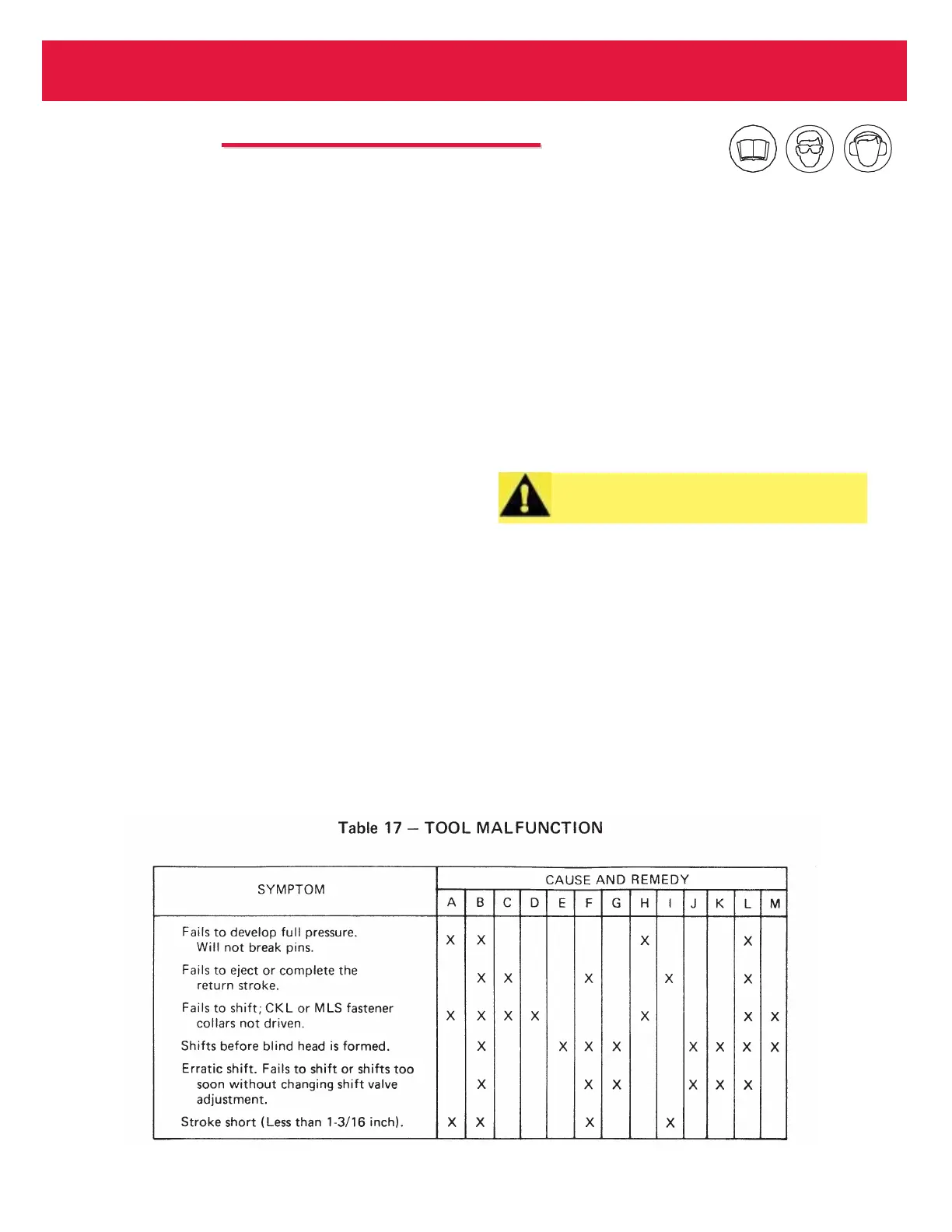
TOOL MALFUNCTION CAUSE AND
TOOL MALFUNCTION CAUSE AND
REMEDY
REMEDY
A. Air supply pressure low. Air pressure of 90-100 psi
required.
B. Air in hydraulic system. Refill and bleed tool per
instructions.
C. Check nose assembly for completeness and prop-
er installation per instructions.
D. Shift valve adjustment set too high (13-7). Readjust
counter-clockwise per instructions.
E. Shift valve adjustment set too low (13-7). Re adjust
clockwise per instructions.
F. Relief valve (13-8) not sealing. Check 3/16 inch
ball (2-47) and seat (2-3) for foreign particles.
Clean if dirty. Reseat ball by tapping against brass
seat. Replace ball or seat if damaged.
G. Check valve (13-9) for leakage. Clean and reseat
ball (2-51) by tapping. If ball or seat (2-2A) are
damaged, replace.
H. Bleed screw (2-40) not backed out to stop (13-11).
Balance valve (2-33) stuck in open position or for-
eign material between valve and seat. Free valve
and remove any foreign particles. If valve or seat
(2-4) are damaged, replace.
I. Check valve (13-10) for leakage. Clean valve and
reseat ball (2-51) by tapping. If ball or seal (2-2B)
are damaged, replace.
J. Shift sleeve (4-27) loose (13-12). Tighten with
Wrench 100878.
K. Shift valve seat (4-13) not sealing (13-13). Replace
seat if foreign particles are imbedded in seal, or if
seat is damaged.
L. Shift plunger (4-10) sticky in sleeve (4-7). Remove
plunger from sleeve. If plunger or sleeve bore is
scored, replace (13-13).
M. Extreme temperature variation. Adjust shift valve
(13-7) as necessary.
CAUTION: Make certain that Valve compo-
nents are not magnetized.