200 Series Tooling Alcoa Fastening Systems
23
M
M
AJOR
AJOR
S
S
UBASSEMBLIES
UBASSEMBLIES
D
D
ISASSEMBLY
ISASSEMBLY
1. Connect to air supply.
2. Depress trigger and remove air supply. (this
moves the air and hydraulic pistons to their full
stroke position).
3. Disconnect air supply.
HANDLE ASSEMBLY FROM CYLINDER
ASSEMBLY
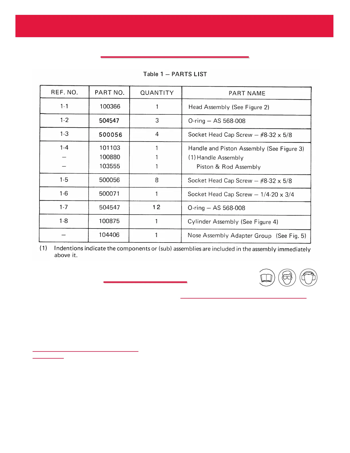
1. Remove eight socket head cap screws (1-5).
2. Remove one socket head cap screw (1-6).
3. Carefully pull handle and piston assembly (1-4)
from cylinder assembly (1-8) in a straight line.
(This will prevent binding of the air piston and
bending of the piston rod).
HEAD ASSEMBLY FROM HANDLE ASSEMBLY
1. Remove four socket head cap screws (1-3).
2. Carefully pull head assembly (1-1) from handle
assembly (1-4).
3. Drain hydraulic fluid.