200 Series Tooling Alcoa Fastening Systems
32
H
H
ANDLE
ANDLE
D
D
ISASSEMBLY
ISASSEMBLY
AND
AND
A
A
SSEMBLY
SSEMBLY
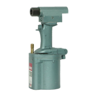
HANDLE DISASSEMBLY
The handle and piston assembly contains a four
way air valve, high pressure air relief valve, trigger
components, hydraulic cylinder, and piston and rod
assembly. Disassemble the handle and piston assem-
bly as follows:
1. Separate head assembly (1-1) and cylinder
assembly (1-8) from handle assembly (1-4)
per instructions in the Major Subassemblies
Section.
2. Using Truarc pliers #0100, Part No. 502857,
remove retaining ring (3-48). Remove piston
(3-44), rod (3-34), intensifier gland (3-35) and
hydraulic piston (3-40) by pulling piston and
rod free of handle.
3. Remove flat head screw (3-43) from rod and
slip hydraulic piston and intensifier gland off
rod. Exercise care to prevent scoring rod.
4. Examine piston, rod, intensifier gland, hy-
draulic piston and all seals for damage. Re-
place parts as required.
5. Acorn nut (3-12) contains a spring-loaded
valve and should be carefully removed along
with spring (3-10) shim(s) (3-9) and valve
(3-8). Remove O-ring (3-11).
6. Remove bolt (3-5) and swivel connector (3-4).
Examine seals on all components for damage
and replace when necessary. Shims (3-9) are
used to obtain 100-110 psi air pressure relief.
7. Hand grip (3-32) is removed by unscrewing
four screws (3-33). Push out pins (3-30) and
remove trigger (3-31) and lever (3-29). Re-
move cross bar (3-28) and four-way air valve
actuating pins (3-23 and 3-27).
8. Remove air valve seat (3-24), front plug
(3-20) and balls (3-22 and 3-26). Remove
rear plug (3-15), spring (3-19) and baIl (3-18).
Inserts (3-2) are press lit.
9. Unscrew filler plug (3-13) and collector (3-49)
and check O-rings (3-14 & 3-50).
HANDLE ASSEMBLY
Before assembling handle piston assembly, clean all
components thoroughly with mineral spirits, and
Iubricate lightly with LUBRIPLATE NO.130AA. Then
assemble handle, following figure 3. Piston and rod
assembly should be assembled last, inserting the
hydraulic piston in the bottom of the handIe. Take
care that rings are not cut or sheared in assembly.
Use Truarc pliers #0100, Part No. 502857 to install
retaining ring (3 -48).