10
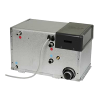
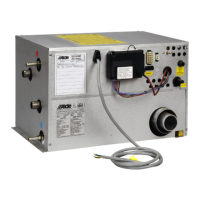
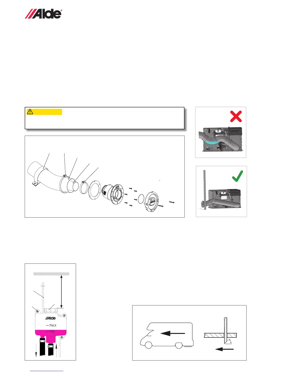
5:6 FITTING THE AIR INTAKE/FLUE EXHAUST HOSE
• Hose length with roof ue: min 2.0 and max 3.5 m.
• Hose length with wall ue: min 0.5 and max 2 m.
• Measure up and cut the required length of air intake hose (Ø 75 mm). The ue exhaust hose (Ø 50 mm) should be
cut so that it is approximately 50 mm longer than the air intake hose. Applies for hose lengths longer than 1 m.
The hoses must go in approx. 20 mm on the pipe connectors.
• Insert the ue exhaust hose into the air intake hose. First, t the ue exhaust hose (Figure C,E 12) to the ue and
secure in place with a hose clip (Figure C,E 13). Then push on the air intake hose (Figure C,E 14) and secure in
place with the other hose clip (Figure C,E 15). After that, t the hoses to the boiler in the same way. Secure the
hose with pipe clamps (Figure E 16)
at 600 mm c/c, or equivalent.
• Check the routing of the air intake/ue exhaust hose to make sure water pockets are not possible in the air intake/
ue exhaust hose. Also check that the hose clips are tted correctly.
Figure E
13
12
14
15
16
CAUTION
OBSERVERA
ATTENTION
VOORZICHTIG
Check the hose routing to ensure that water cannot be retained in the inlet/ex-
haust hose.
18
Figure G
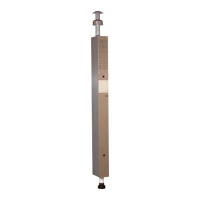
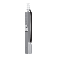
5:7 FITTING THE EXPANSION TANK
• Fit the expansion tank at least 200 mm higher than the highest point of the heating system. Leave a space of at least
220 mm above the expansion tank for lling and servicing purposes. Fit the expansion tank using the enclosed screws
and grommets (Figure F 16).
• If a circulation pump is to be tted in the expansion tank, it will be the suction pump type. For this reason, incom-
ing hoses must be connected to the pipe underneath the pump and outgoing hoses to the pipe alongside it (see
Figure F). The air vent hose (Figure F 17) has to be tted vertically and secured in place with pipe clamps to pre-
vent the hose from creasing. The drain hose (Figure F 18) has to be tted so that it fol-
lows the shortest route from the expansion tank and out through the oor of the vehicle.
Cut the hose obliquely under the vehicle at an angle of 30° facing the rear of the vehicle
(Figure G). Once the heating system has been lled, any optional pump is tted in the tank
and secured in place with nut (Figure F 19). Then, t the contact to the pump to the "right
place" on the circuit board. (Figure K 7, page 9).
min 220 mm
Figure F
17
16
19
 Loading...