EasyManuals Logo

Alde Compact 3020 HE Installation Instructions

Alde Compact 3020 HE
32 pages
To Next Page IconTo Next Page
To Previous Page IconTo Previous Page
Page #18 background imageLoading...
Page #18 background image
18
Control panel rear
3020
+
Battery Back-up (3V DC)
Remote Sensor 1
Remote Sensor 2
Sofa
Bed
Heater
CI Bus
External panel
Mechanical panel 3010 214
Fuse 3,15 A
12 V DC
12 V
pump
Control panel
Tin bus
Option board/
Mechanical panel
External
start
Window
sensor
Load
monitor
Outdoor
sensor
D
E
I
F
Circuit board on
Compact 3020 HE boiler
CI Bus connection
NOTICE
Do not clamp or bind 12V cables or sensor cables
together with 230V cables. The cables should prefer-
ably not be placed close to each other. If the cables are
bundled, the risk of malfunction increases.
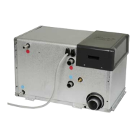
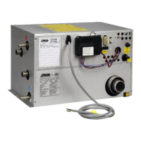
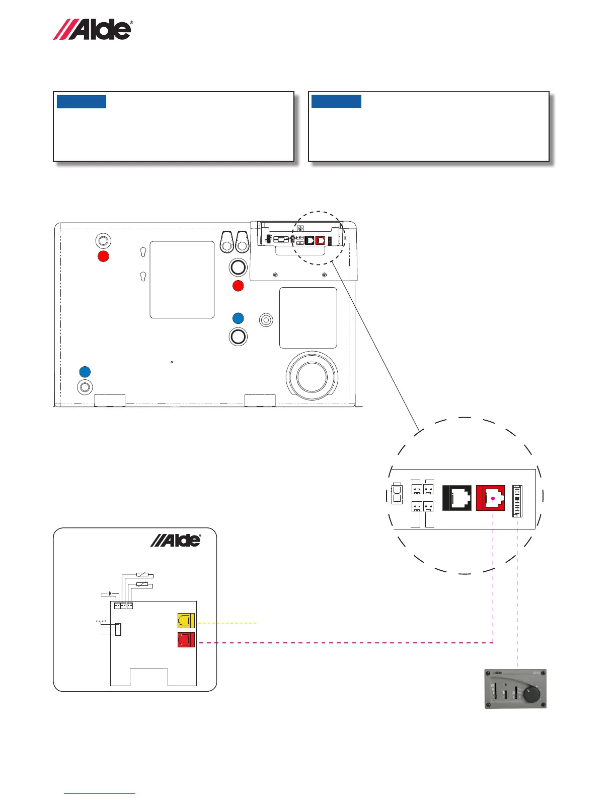
8:1 CABLE CONNECTION COMPACT 3020 HE AND CONTROL PANEL
Connect the boiler and control panel as shown in the diagram below.
NOTICE
To protect against malfunction only use original Alde
cables, shielded cable for EMC.

Other manuals for Alde Compact 3020 HE

Questions and Answers:

Question and Answer IconNeed help?

Do you have a question about the Alde Compact 3020 HE and is the answer not in the manual?

Alde Compact 3020 HE Specifications

General IconGeneral
BrandAlde
ModelCompact 3020 HE
CategoryBoiler
LanguageEnglish

Related product manuals