3
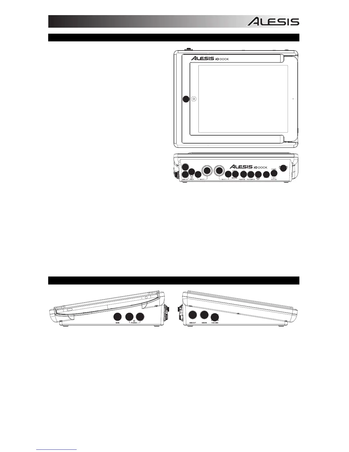
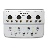
TOP & REAR PANEL FEATURES
1. DOCK – Connect your iPad here.
2. DC INPUT – Connect the included power
adapter (6V, 3A) here, then connect the
adapter to wall power.
3. POWER SWITCH – Turns the iO Dock on
and off.
4. CABLE RESTRAINT – To prevent
accidentally unplugging, wrap the power
adapter cable around this restraint.
5. MAIN OUT – Use standard 1/4" TRS cables
to connect these outputs to a speaker or
amplifier system. The level of these outputs
is controlled by the MAIN knob.
6. DIRECT MONITORING SWITCH – Set this
switch to "ON" to listen directly to your input
sources without any processing from the
iPad.
7. MIC/LINE INPUT – Connect a microphone or
line-level device to this input with an XLR or
1/4" TRS cable.
8. GUITAR / MIC/LINE INPUT – Connect a
microphone, line-level device or guitar to this input with an XLR or 1/4" TRS cable.
9. GUITAR / MIC/LINE SWITCH – When this switch is in the "GUITAR" position, the channel will serve as
a high-impedance input for connecting guitar or bass instruments. When the switch is in the "MIC/LINE"
position, the channel will accept mic or line-level signals.
10. GAIN – Adjusts the input's gain level.
11. PHANTOM POWER SWITCH – This switch activates and deactivates phantom power. When
activated, phantom power supplies +48V to both XLR mic inputs. Please note that most dynamic
microphones do not require phantom power, while most condenser microphones do. Consult your
microphone's documentation to find out whether it needs phantom power.
12. FOOTSWITCH – Connect a remote footswitch to this input with a 1/4” cable. Pressing the footswitch
will alternately send MIDI start or stop messages to the iPad.
13. VIDEO OUT – Use a standard composite video cable (RCA) to connect this output to the composite
video input of your playback device.
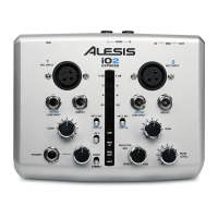
SIDE PANEL FEATURES
123
4
5
6
1. MAIN VOLUME – Adjusts the output volume of the MAIN OUT.
2. PHONES VOLUME – Adjusts the output volume of the PHONES output.
3. PHONES – Connect a set of 1/4" TRS headphones to this output.
4. MIDI OUT – Use a standard five-pin MIDI cable to connect this output to the MIDI IN of an external
MIDI device.
5. MIDI IN – Use a standard five-pin MIDI cable to connect this input to the MIDI OUT of an external MIDI
device.
6. USB MIDI – This connection will allow you to send MIDI information to/from a computer. Use a USB
cable to connect the iO Dock to a computer. iO Dock requires a USB 1.1 or higher (e.g. USB 2.0)
connection. (Note: Audio will not pass over this connection.)
1
5
2
3
4
5
6
7
10
10
9
11
12 13
8