Do you have a question about the Alesis QS Series and is the answer not in the manual?
Important legal and usage terms and conditions for the service manual.
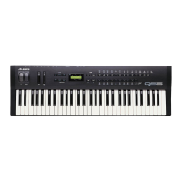
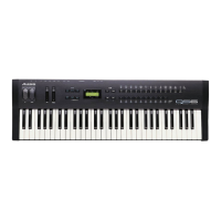
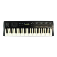
Details on the QS6 model, its features, and PCB revisions.
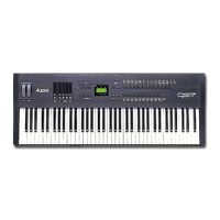
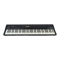
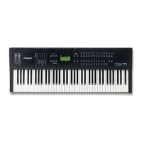
Details on the QS7 model, its features, and PCB revisions.
Details on the QS8 model, its features, and PCB revisions.
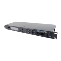
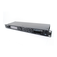
Details on the QSR rack mount model and its PCB revisions.
Description of the power supply circuits for QS6/QSR and QS7/QS8 models.
Overview of analog signal flow, including main and headphone outputs.
Explanation of digital signal processing and component interactions.
Specifics on the AKM4318A DAC used in the S6 model.
Specifics on the AKM4319 DAC used in QS7/QS8/QSR models.
Details on serial data transmission and reception for PC/MAC interfaces.
Explanation of the switch for selecting PC or MAC serial interface modes.
Accessing and performing automated and individual hardware self-tests.
Detailed description of each self-test routine available in individual mode.
Procedure for testing the 48KHz digital audio input functionality.
Steps for opening the unit and reassembling it safely.
Instructions for replacing major parts like the keyboard or individual keys.
Pin diagram for the Sound Generator ASIC.
Pin diagram for the Effects ASIC.
Pin diagram for the Keyboard Scanning ASIC.
Pin diagram for the H8 Microprocessor.
Pin diagram for the Static RAM chip.
Pin diagram for the Erasable Programmable Read-Only Memory chip.
Pin diagram for the Sound ROM chip.
Pin diagram for the Gate Array Logic chip.
Pin diagram for the Digital-to-Analog Converter chip.
Specific changes documented for QS6 main PCB revisions B through F.
Specific changes documented for QS7/8 main PCB revisions B through F.
Notes on changes made to the VCO circuit affecting QS7/QS8 units.
Chronological list of software updates and bug fixes for the QS6.
Chronological list of software updates and bug fixes for the QS7/QS8.
Chronological list of software updates and bug fixes for the QSR.
Details on the MIDI System Exclusive message format for the QS6.
Parameter details for effect configuration 0, including delay and reverb sends.
Parameter details for effect configuration 2, including lezlie effects.
Parameter details for effect configuration 3, including EQ and sends.
Parameter details for effect configuration 4, including various effects.
List of parts specific to the Alesis QS6 synthesizer.
List of parts specific to the Alesis QS7 synthesizer.
List of parts specific to the Alesis QSR synthesizer.
List of parts specific to the Alesis QS8 synthesizer.
| Multitimbral | 16 parts |
|---|---|
| Oscillators | Sample-based |
| Effects | Reverb, Chorus, Delay, EQ, Distortion |
| Display | LCD |
| MIDI | In, Out, Thru |
| Memory | User Programs |
| Outputs | Stereo |
| Weight | 11 kg |