Maintenance
Step 6
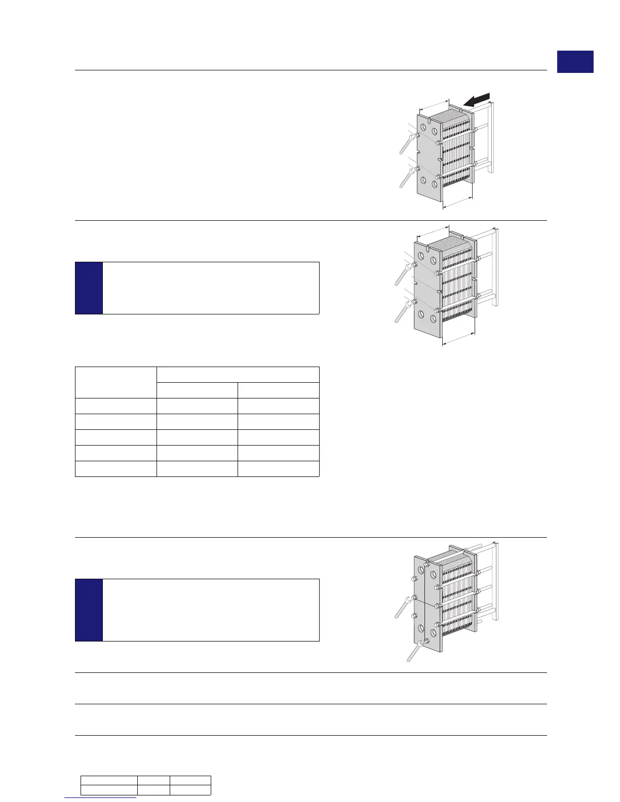
Press the plate pack together. Posit ion the fou r tightening bolts
according to the figure.
Tighte n the four bolts (1), (2), (3), (4) until the plate pack
measure A is 1.10 making sure the frame plate and pressure
plate are parallel when closing.
Step 7
Tighte n the four bolts (1), (2 ), (3), (4) evenly until dimension A
has bee n reached.
Note!
For TL6: Add the middle bolts and continue to tighte n 1 0
m m or less with bolt 5 and 6. Then tighte n the remaining
bolts with the same length. Repeat these steps until
dimension A is achieved.
When a pneumatic tightening device is used, see table below for
maximum torque. Measure dimension A during tig htening.
Bolt with washerBolt size
Nm kpm
M 10 32 3.2
M 16 135 13.5
M 20 265 26.5
M 24 450 45
M 30 900 90
For manual tightening, the tightening torque has to be estimated.
If dimension A cannot be reached:
• Ch eck the number of plat es and the dimension A.
• Ch eck that all the nuts and bearing boxes are running freel y.
If not, clean and lubricate, or r eplace.
Step 8
Mount the remaining locking bolts and check measurement A
on both sides, top and bottom.
Note!
For TL6: When using frame ASME standard! Heat
excha ngers with pressure vess el code ASME are
equipped with top and bottom bolt s. Tighten those bolts
after th e procedure above has been finished or slightly
before the dimension A is reached.
Step 9
Mount protection sheets (if provided).
Step 10
Connect pipes .
Document ID La nguage Edition
3490010217 EN 2016-06 Instruction Ma nual - Plate Heat Exchan gers 27
EN
 Loading...