1.IfF~I!!i!:DC 4.5V-6Vo
2
·)~f.6~)nt: <20mA@4. 8V °
3.rnH~i~)Jj~§I~~~ °
4 ·~~w~: 10500-21000RPM °
5 .iq]~~35PWM.:±J)BZJil-2ms ' ~~ffl S9251 'S9256~760 ~ Siq]~~35 °
6 .IfF)lili~iQ:~-20°C-85°C °
7 .Ii'F)!ffi~w~: 0%-95% °
8 ·:zts:~9'}m1RIJ:28. 5x26. 2x9mm °
9·&R5m*~~:160mmo
10 ·~~@\JjIJ~~: 250mm
°
ll.~.: 109(~tJU~)°
12 .!!GiCj::~~@\Elm.x2pcs °
*~ill!pj7\J3'3t~**CT2. 6x6) x2pcs °
~~35~~@x1pc °
CH1
CH2
CH3
CH4
CH5
CH6
AUX
Receiver
(7 Channelor more)
U1Ji'IOl).(J:m1&~
Throttle servo
;iBF~iOI!~~
STATUS
.L\LlGN
RCE-1i6UU ~w
ENGINE GOVERNOR ~ +
Throttle travel setting
;iBF~iJ'!~09:JEiJJ'
Sensor
QJEIW~~
Indicating light
Red: Governor OFF
Green: Governor ON
ilAl!!\j~;j;m
!i[:JFJE~
IiI<:JE~
Specifications ~6iHJHe/I§GI!:j:
1.0perating voltage:DC4.5V-6V
2.Consumption current: <20mA@4.8V
3.Direct detection of engine rotation speed
4.Speed control range: 10500-21 OOORPM
5.Servo RWM output pulse width: 1-2ms,
not apply to S9251 ,S9256,other 760
/.L 5 servos.
6.0perating temperature range:-20°C-85°C
7.0perating moisture range:0%-95%
8.Case size(body):28.5x26.2x9mm
9.Signal wire lel1gth: 160mm
1O.Sensor wire length:250mm
11.Weight: 1Og(including wires)
12.Accessories: Magnet x 2pcs
Screw (T2.6x6) x 2pcs
Governor mount x 1pc
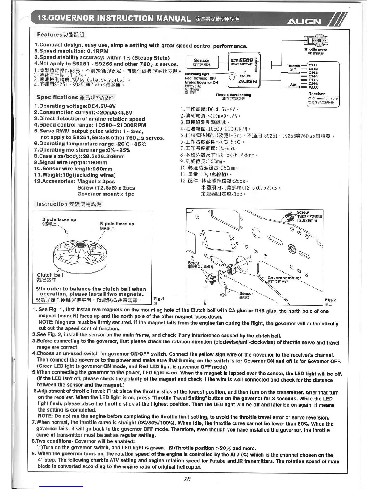
1.Compact design, easy use, simple setting with great speed control performance.
2.Speed resolution: 0.1 RPM
3.Speed stability accuracy: within 1% (Steady State)
4.Not apply to S9251 ' S9256 and other 760
/.LS servos.
1.~~Mfj.~.~,~~ •• ~~~,~.~.~~~~~~o
2 ·~~~;ffT~O.l RPM°
3 .~~:JSgflj~M~l%Ji.Zpj (steady state) °
4 ·~~fflS9251 'S9256~760 ~ Siq]~~35 °
*In order to balance the clutch bell when
operation, please install two magnets.
*~3.~35••~~E'm.~@.~~.o
N pOle faces up
Nto]WJJ:
S pole faces up
sto]WJJ: ~
~i~.1 H '00"""" ~ '\ I ~i~.2
1. See Fig. 1, first install two magnets on the mounting hole of the Clutch bell with CA glue or R48 glue, the north pole of one
magnet (mark N) faces up and the north pole of the other magnet faces down.
NOTE:Magnets must be firmly secured. If the magnet falls from the engine fan during the flight, the governor will automatically
cut out the speed control function.
2.See Fig. 2, install the sensor on the main frame, and check if any interference caused by the clutch bell.
3.Before connecting to the governor, first please check the rotation direction (clockwise/anti-clockwise) of throttle servo and travel
range are correct.
4.Choose an un-used switch for governor ON/OFFswitch. Connect the yellow sign wire of the governor to the receiver's channel.
Then connect the governor to the power and make sure that turning on the switch is for Governor ON and off is for Governor OFF.
(Green LEDight is governor ON mode, and Red LEDlight is governor OFF mode)
5.When connecting the governor to the power, LEDlight is on. When the magnet is lapped over the sensor, the LEDlight will be off.
(If the LEDisn't off, please check the polarity of the magnet and check if the wire is well connected and check for the distance
between the sensor and the magnet.)
6.Adjustment of throttle travel: First place the throttle stick at the lowest position, and then turn on the transmitter. After that turn
on the receiver. When the LED light is on, press "Throttle TravelSetting" button on the governor for 3 seconds. While the LED
light flash, please place the throttle stick at the highest position. Then the LEDlight will be off and later be on again, it means
the setting is completed.
NOTE:Do not run the engine before completing the throttle limit setting, to avoid the throttle travel error or servo reversion.
7.When normal, the throttle curve is straight (0%/50%/100%).When Idle, the throttle curve cannot be lower than 50%. When the
governor fails, it will go back to the governor OFF mode. Therefore, even though you have installed the governor, the throttle
curve of transmitter must be set as regular setting.
8.Two conditions- Governor will be enabled:
(1)Turn on the governor switch, and LEDlight is green. (2)Throttle position >30% and more.
9. When the governor turns on, the rotation speed of the engine is controlled by the ATV (%) which is the channel chosen on the
4th step. The following chart is ATVsetting and engine rotation speed for Futaba and JRtransmitters. The rotation speed of main
blade is converted according to the engine ratio of original helicopter.
28