Features JJJ§~IDt IJI3
1.Due to the unique 2 in 1 design, the regulator's functions provide power to the receiver, servos, and the internal glow plug
ignition system that does not require you to remove the clip lead.
2.The linear regulator design results in no interference to the receiver. The required input power may only consist of a 2 cell
Li-ion or a Li-Poly battery.
3.When the integrated power switch is moved to the on position, the voltage indicating LED's and ignition indicating LED's will
illuminate displaying thestatus of the battery voltage, and of the plug ignition function.
1. J;~B~CEi-5)t5t '
~3 ~jil\j CBED~/.Im*M ' J~.lj~ij:H~l&:35~jqJ§IR35~)~Ii'DJJJ~g9i-' ~pj~-*§*~IHi~Ii'D~D*~~ ' !§:J8PjIM~3R:tElJWli'DlI11Lrj:[0
2·::$:~B5:1*m*&;JI'1~5t ' il®7\~)~i102CELLm i-ionQ'ZLi-Poly~)tB, ~ill~DiI0::f~j~3Z~J:\;~5tIi'DBEC~~±TJ\I:I~1&:35Ii'DJI~JB ' ~D~t$~Ii'D;I!Jd~ 0
3. ~iil\j~)~~1#J ' ~Im:l~jf-;mB.~D*:I~7fJ~JJJ~g , DJEI3~~5m*UAE~)tB~ii~*~¥Ii'D~D*;t\!m 0
Receiver and Servo Voltage Regulating Functions:
1.The Auto-detecting voltage LED's will display a series of lights when turned on. If the entire five-light array is illuminated then
the battery is fully charged.When the voltage drops below 7.6V the three green lights will turn off. USE CAUTION: Once the
green lights are no longer illuminated the battery can only be safely used for a single flight. When only the single red LED is lit,
DO NOT ATTEMPT TO OPERATE THE MODEL The battery voltage has been drained too low, and must be recharged before its
next use.
2.lt is important to note that not all servos are designed to operate on 6 volts, such as Futaba servo models 9241, 9251,9253,
9254, 9255, 9256 and other digital servo are not capable of handling 6V. Please check with the manufacturing specifications
of the servo before attempting to operate. A separate 5.1V inline voltage Step-Down may be purchased and is recommended
for use between the gyro and the tail servo, and any servos that are not designed to handle 6V. Please note that some servos
are designed for running on 6V and may not require a voltage step-down.
ml&:~~iqJ§&~~j~a~iB :
1. ::$:~B5~~m:l~jf-;JJJ~g , ~m7\ftff@Ii'D~)tB8i!fE!IIM~jf-;~~~~ ' ~jf-;~)tBifFull~iiftJEiIt!ml': i£Emcp~~Im~itl;~7. 6V8i!f(3!11~*~~~~\iJ)~), ~DJ7'(:
px~!E@~{jlm~j:[1t>t~)tBft~Q'Z~~WT~)tB ; rm~O~iJi~KtU~8i!f~jf-;Empty~ii::fJE ' ::f1il~j'iji£Em~
!
2. ffi\{Bli'Diq]§fii35~O:Futaba9241. 9251. 9253.9254.9255. 9256~ ' JtL;@!~li'Diq]§fii35::f@:EiD~'~~Ii'D~lml':I*fF' J5ffUi£EmJtL;@!~li'Diq]§fii358i!f5~§59i-JJO~5.1V
~1m~~35D~~'8t*j~~~ffi8iq]§fii35r.IJ ' W¥~jqJ§fii35:1~~;~JI,t6~jf-;)1i5q:6VWil7\li'Diq]§fii35J'1U::f~j:[i£Em~~35
0
Glow Plug Ignition System Functions:
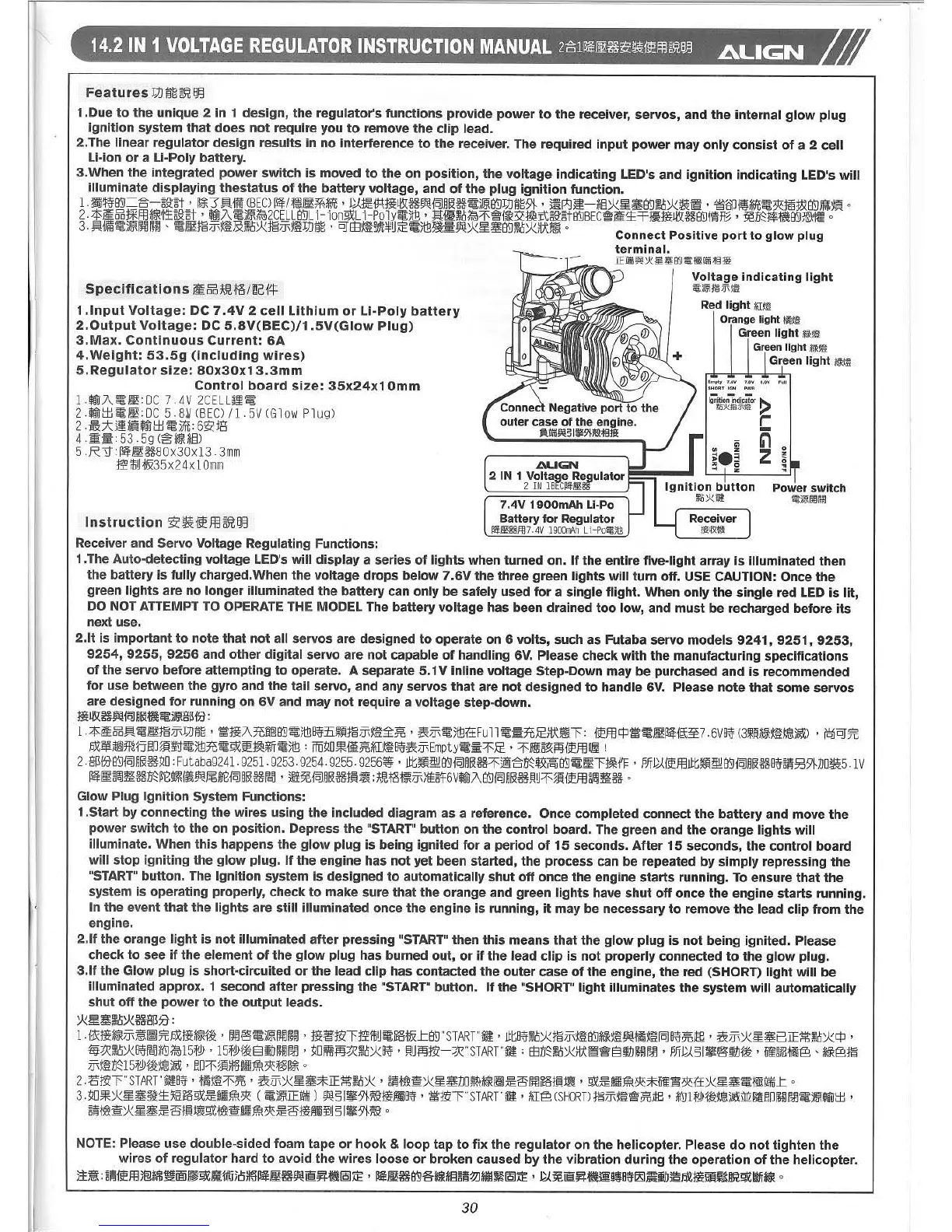
1.Start by connecting the wires using the included diagram as a reference. Once completed connect the battery and move the
power switch to the on position. Depress the "START" button on the control board. The green and the orange lights will
illuminate. When this happens the glow plug is being ignited for a period of 15 seconds. After 15 seconds, the control board
will stop igniting the glow plug. If the engine has not yet been started, the process can be repeated by simply repressing the
"START" button. The Ignition system is designed to automatically shut off once the engine starts running. To ensure that the
system is operating properly, check to make sure that the orange and green lights have shut off once the engine starts running.
In the event that the lights are still illuminated once the engine is running, it may be necessary to remove the lead clip from the
engine.
2.lf the orange light is not illuminated after pressing "START" then this means that the glow plug is not being ignited. Please
check to see if the element of the glow plug has burned out, or if the lead clip is not properly connected to the glow plug.
3.lf the Glow plug is short-circuited or the lead clip has contacted the outer case of the engine, the red (SHORT) light will be
illuminated approx. 1 second after pressing the "START" button. If the "SHORT" light illuminates the system will automatically
shut off the power to the output leads.
*~¥~D*~g~:B :
1.i?\:I~*~jf-;~~7'(:pxm*~j~ ' ~@:~)~~~~ ' m~:lgz>Tjggi1JU~~t&-'=Ii'D"START"~' JtL8i!f~D*mjf-;~~Ii'D*~m~t~H~[q]8i!f~iE8' ~jf-;*~¥8IE*,~.o*CP ,
~~~D*8i!fr.IJ;\'{!JiI015f''»' 15f''»{~E1i1J1#J~' ~O~j'ij~~D*8i!f ' J'1Uj'ij:lgz>-~"START"~; EED~~D*;t\~~E1i1JI#J~ ' J5ffU§I~@:i1J{~ ' ii~~fgmES' *~@~
jf-;mD~15f''»{~~\iJ)~' 1.m::f~j:[~;~JIHi1t3R:f~~
0
2.fimrSTART"ii9t8i!f ' m~~::f;ffi, £Zjf-;*~¥*IE*,~D* ' ~~tJH!~*~¥JJOAA*~~~6~~i~~ ' Q'Z~~;~3R:*ii~.3R:if*~¥~to]!iffij-,= 0
3.~O~*~~5~±lH~Q'Z~~;J'i1t~ (~)~IE!iffij) ~§I~9}m1mi!i8i!f ' ~:lgz>rSTARnl ' KiIES(SHORTJ:I~jf-;~~~~iE8' ;\'{!Jm~~~,)~j'[(zi>Ji1101#J~~)~Wilt±J'
~~m~*~~~6:1~j~Q'Zm~~;~3R:~6mi!i3W§I~9i-m1
0
Specifications ~§jHJI,te/~Gi!:J:-
1.lnput Voltage: DC 7.4V 2 cell Lithium or Li-Poly battery
2.0utput Voltage: DC 5.8V(BEC)/1 .5V(Glow Plug)
3.Max. Continuous Current: 6A
4.Weight: 53.5g (including wires)
5.Regulator size: 80x30x13.3mm
Control board size: 35x24x1 Omm
1 .iI®7\ ~ m: 0C 7. 4V 2CELL£!~
2.iI®t±J~I!E:OC 5.8~(BEC)/l.5V(Glow Plug)
2. m:A~*liil® t±J~)Jit: 6~Jg
4 .~ii: 53. 5g (~*~*.§)
5 .R~:~1m3580x30x13. 3mm
~i1Jut&35x24x10mm
Instruction
3Z'~i~mIDtIJl3
Connect Positive port to glow plug
terminal.
lEiffifiW*~¥9'9~@iffifit§*
Voltage indicating light
i~J~
f~m ~~
Red light i\I:®'
Orange light mm'1
Green light ~j~
Green light it'R:®'
Green light ~j~
.L\UGN
2 IN 1 Voltage Regulator
2 IN IBrCII1!;!i!6
7.4V 1900mAh Li-Po
Battery for Regulator
1I1!J!!iii!§ffl7.4V 1900ll\'\h Li-Po~jtIJ
NOTE: Please use double-sided foam tape or hook & loop tap to fix the regulator on the helicopter. Please do not tighten the
wires of regulator hard to avoid the wires loose or broken caused by the vibration during the operation of the helicopter.
51~: ~~liEm)B!MJ~[§jn1S~~1iI'q5rHI~~~~~~¥I-~~AE ' ~~~~~*&;*g~~:m~4EJ:M~AE ' P..1.~~¥I-~ji.!8~12SI~i1J~pxmgU~Im~IWi*,'R
0
30