EasyManua.ls Logo

Alinco DJ-S1E User Manual

Alinco DJ-S1E
46 pages
To Next Page IconTo Next Page
Page #1 background imageLoading...
Page #1 background image
VHF FM HANDHELD TRANSCEIVER
UHF FM HANDHELD TRANSCEIVER
Service M anual
-----------------------------------CONTENTS
-----------------------------------
SPECIFICATIONS........................................................ 1
DJ-F1T/E CABINET PARTS LOCATION
.................................
2
M67748L1 (MAIN UNIT IC-201)
........................................
3
MB1504L (MAIN UNIT IC-202)
.........................................
4
TK10487MT (MAIN UNIT IC-203)....................................... 5
¡I PD4094BG (MAIN UNIT IC-204)...................................... 6
NJM386M (MAIN UNIT IC-205)
.........
...............................
7
M5236ML (MAIN UNIT IC-206)
.........................................
8
M5218 (MAIN UNIT IC-207)............................................. 9
CM8880 (DTMF UNIT IC-601)...........................................10
TM8880 (DTMF UNIT IC-602)........................................... 10
MPD78214GC582-AB8 (CPU UNIT IC-02)..............................11
S-81250HG (CPU UNIT IC-03)
.......................................... 12
S-8054HN (CPU UNIT IC-04)............................................13
DJ-F1T/E DJ-S1T/E PARTS LIST
.......................................
15
ADJUSTMENT F1-T/S1-T
...............................................
18
ADJUSTMENT F1-E/S1-E
...............................................
19
SCHEMATIC DIAGRAM..................................................20
VR.RE.SW.PC BOARD...................................................22
CPU PC BOARD..........................................................23
VCO PC BOARD..........................................................27
MAIN PC BOARD........................................................28
KEYBOARD.............................................................. 32
EMS-8 (Remote control Speaker/Microphone)........................33
EME-10K (Headset W/PTT VOX)
.......................................
34
SCHEMATIC DIAGRAM OF EME-10K
................................... 35
EME-10K PC BOARD.....................................................36
EJ-10U (DTMF ENC/DEC UNIT)......................................... 37
EJ-10U (DTMF PC BOARD)..............................................38
EJ-12U (TONE SQUELCH UNIT)........................................ 39
PC BOARD OF TONE SQUELCH UNIT
..................................
40
EDC-34 (QUICK CHARGER 120V)
......................................
41
EDC-35 (QUICK CHARGER 220V)
......................................
42
ALINCO ELECTRONICS INC.

Other manuals for Alinco DJ-S1E

Question and Answer IconNeed help?

Do you have a question about the Alinco DJ-S1E and is the answer not in the manual?

Alinco DJ-S1E Specifications

General IconGeneral
ModulationFM
Receiver SystemDouble Conversion Superheterodyne
TypeHandheld
Frequency Range144-146 MHz
Channel Capacity200
Battery LifeApprox. 8 hours
Weight220g (with battery)
Voltage7.2V
BatteryLi-ion battery pack

Summary

Specifications

General Specifications

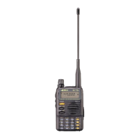
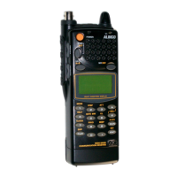
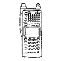
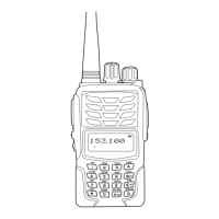
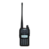
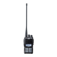
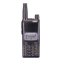
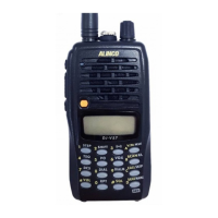
Covers frequency coverage, memory channels, emission type, dimensions, and weight.

Transmitter Specifications

Details output power, modulation system, frequency deviation, and spurious emission.

Receiver Specifications

Specifies receiving system sensitivity and intermediate frequencies.

DJ-F1T/E Cabinet Parts Location

Mechanical Parts List

Lists all mechanical components and their part codes for the transceiver.

Screw List

Lists all screws used in the transceiver assembly and their specifications.

DJ-F1T/E DJ-S1T/E Parts List

CPU Unit Components

Detailed list of components for the CPU unit, including part codes and names.

VCO Unit Components

Lists components for the VCO unit with part codes and names.

Main Unit Components

Lists components for the main unit, including ICs, transistors, and passive components.

Adjustment F1-T/S1-T

Standard Frequency & Output Power

Procedures for setting frequency and adjusting output power levels.

Transmitting Spurious & Modulation Adjustments

Verifying spurious emissions and adjusting modulation.

VCO Voltage & Air Band/VHF Adjustments

Adjusting VCO voltage, AIR BAND, and VHF front-end.

S Meter Adjustment

Procedure for calibrating the S meter.

Adjustment F1-E/S1-E

Standard Frequency & Output Power

Procedures for setting frequency and adjusting output power levels.

Transmitting Spurious & Modulation Adjustments

Verifying spurious emissions and adjusting modulation.

VCO Voltage & Air Band/VHF Adjustments

Adjusting VCO voltage, AIR BAND, and VHF front-end.

S Meter Adjustment

Procedure for calibrating the S meter.

Schematic Diagram

VR.RE.SW.PC BOARDS

CPU PC Board Layout

VCO PC Board Layout

Main PC Board Layout

Key Board Layout

EMS-8 Remote Control Speaker/Microphone

EME-10K Headset W/PTT VOX

Schematic Diagram of EME-10K

EME-10K PC Board Layout

EJ-10U DTMF Enc/Dec Unit

DTMF PC Board Layout

EJ-12U Tone Squelch Unit

Tone Squelch Unit PC Board Layout

EDC-34 Quick Charger 120V

EDC-35 Quick Charger 220V

Block Diagram

Related product manuals