EasyManuals Logo

ALLEN & HEATH GL4000 Service Manual

ALLEN & HEATH GL4000
98 pages
To Next Page IconTo Next Page
To Previous Page IconTo Previous Page
Page #28 background imageLoading...
Page #28 background image
Allen & Heath AP2794 issue 3 5
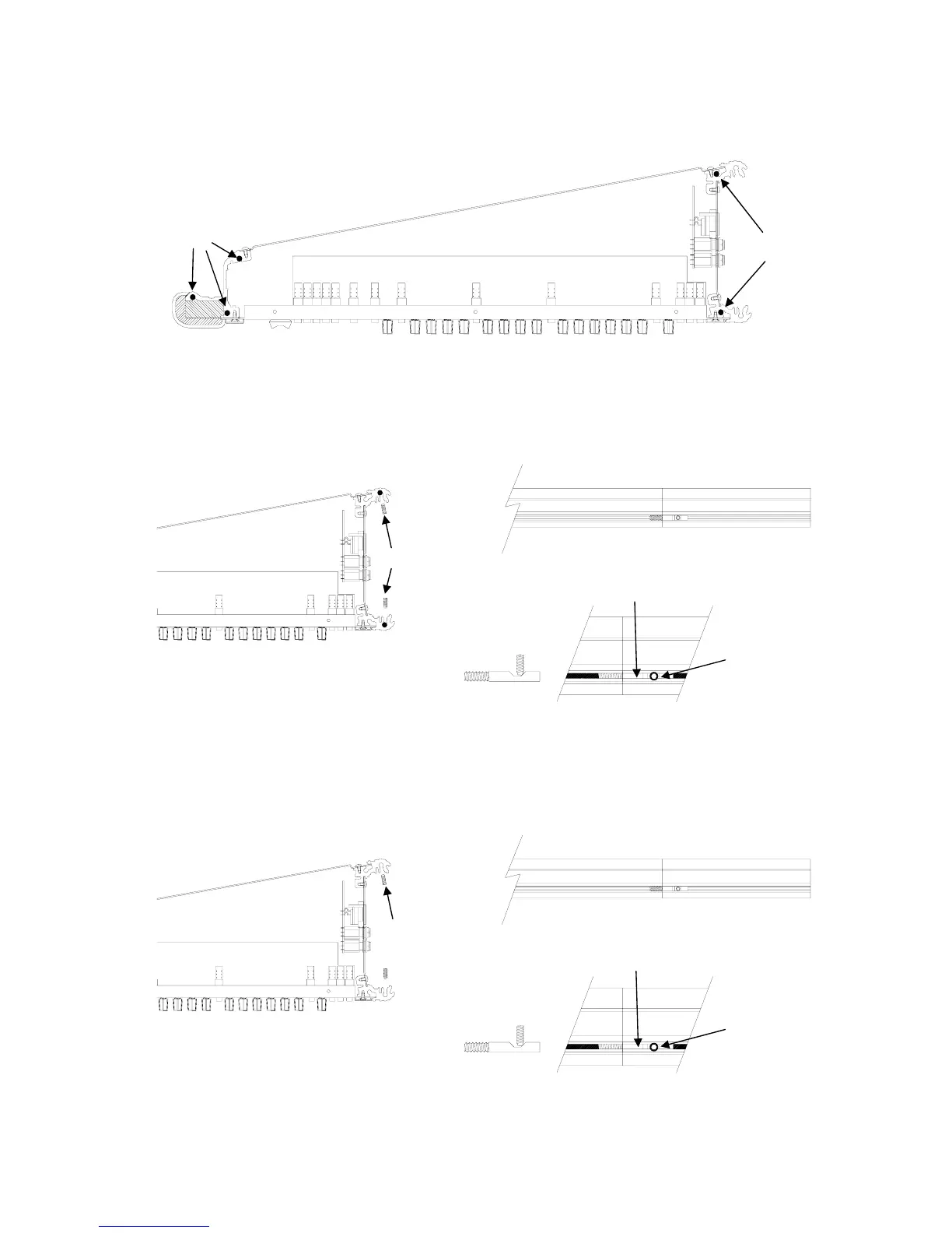
7. Screw the 5 plain studs
‘H’ into the extrusion holes of the expander as shown below.
8. Slide the expander module onto the 7 studs and close the adjustable fastener ‘B’ over the catchplate ‘A’,
see 5. The fastener can be adjusted to ensure a good join. Screw in the locking screws
‘C’ into the pre-
tapped holes of the expander. Make sure the locking screws
‘C’ engages with the flat of the slotted studs
‘J’, see diagram below.
Console with integral meterbridge
8a. Slide the expander module onto the 6 studs and close the adjustable fastener ‘B’ over the catchplate ‘A’,
see 5. The fastener can be adjusted to ensure a good join. Screw in the locking screw
‘C’ into the pre
tapped hole of the expander. Make sure the locking screw
‘C’ engages with the flat of the slotted stud ‘J’,
see diagram below.
expander
H
H
C
J
J
C
console expander
ex
p
ande
r
C
ex
p
ande
r
C
J
J
C
console expander
C

Other manuals for ALLEN & HEATH GL4000

Questions and Answers:

Question and Answer IconNeed help?

Do you have a question about the ALLEN & HEATH GL4000 and is the answer not in the manual?

ALLEN & HEATH GL4000 Specifications

General IconGeneral
TypeAnalog Mixing Console
Groups8
Faders100mm
Frequency Response20Hz - 20kHz
Channels40
Mic/Line Inputs40
EQ4-band with 2 sweepable mids
Direct OutputsYes
Phantom PowerYes
MeteringLED
Total Harmonic Distortion< 0.005% at 1kHz
Noise (EIN)-128dB
DimensionsVaries depending on frame size. e.g., 40 channel: 1367mm (W) x 724mm (D) x 223mm (H)

Related product manuals