ALLEN & HEATH
GL4000 SYS-LINK OPTION
3
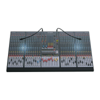
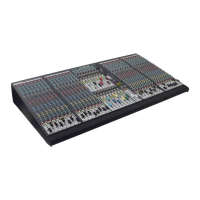
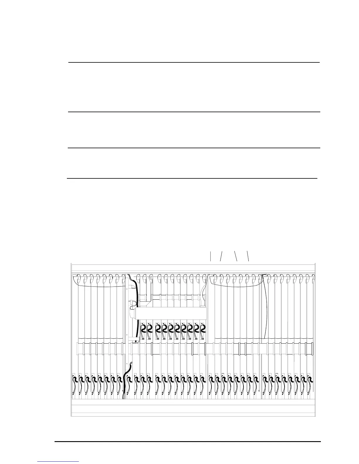
CONSOLE FRONT
GL4000-824 inverted with the base cover removed.
E
fig. 2
Chan
24
Chan
1
REMOVE THE INPUT CONNECTOR CIRCUIT BOARD ASSEMBLY:
The INPUT CONNECTOR circuit board assembly (A) directly behind the SYS-LINK connector mountings on
the rear panel must be removed to gain access to the SYS-LINK D type connector mounting holes.
Follow the procedure below:
1 Unscrew the 16 XLR mounting screws and remove the 32 jack socket nuts on the rear connector
panel.
2 Disconnect the 8 flexible flat cables (C) from the INPUT CHANNEL circuit board assemblies.
3 Disconnectd the ribbon harness (D)
4 Carefully remove the INPUT CONNECTOR circuit board assembly (A) and place to one side.
5 Now remove the SYS-LINK blanking plate.
B
C
D
A
Only technically competent personel should attempt to fit the SYS-LINK option.
Disconnect the Power Supply Unit and cables from the console before fitting
the expander module.
ss
ss
s
PRELIMINARY:
To fit the SYS-LINK option it is necessary to partially remove the INPUT CHANNEL circuit board assembly
next to the GROUP 1 circuit board to enable access to the SYS-LINK circuit board mounting holes. The
INPUT CONNECTOR circuit board assembly behind the SYS-LINK D type connector mounting holes on
the rear panel will also have to be removed. It is not necessary to remove any other circuit board assemblies
as access to the SYS-LINK connections can be made with a pair of long nose pliers.
REMOVE THE KNOB CAPS:
Pull off the knob caps and unscrew the nuts from the INPUT CHANNEL next to GROUP 1 channel. The
switch caps can remain in place.
Remove the optional Meterbridge if fitted.
REMOVE THE CONSOLE BASE :
Carefully invert the console and remove the base panel by removing all screws along the edges of the base
panel. Also remove the 3 screws in the centre of the largest panel
rr
rr
r
pp
pp
p
qq
qq
q
 Loading...