2–11Installation
Publication 1203–5.1 –– July, 1997
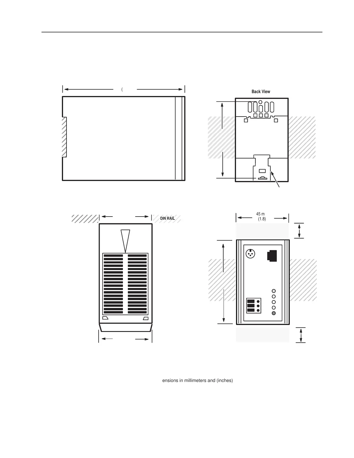
Figure 2.10
Enclosed Style Communications Module Dimensions
DIN RAIL
45 mm
All dimensions in millimeters and (inches)
(1.8)
Back View
(4.8)
123 mm
Side View
(1.8)
45mm
(1.75)
44 mm
Note: The enclosure requires clearance at the top and bottom for
proper cooling. Additional space will be required if access to DIP
switches is desired without having to remove the device.
Front View
Top View
25 mm
(1)
DIN rail mounting
clip
25 mm
(1)
70 mm
(2.7)
DIN
RAIL
DIN
RAIL
76 mm
(3.0)
DIN RAIL

 Loading...