3–11Configuration and Interfacing
Publication 1203–5.1 –– July, 1997
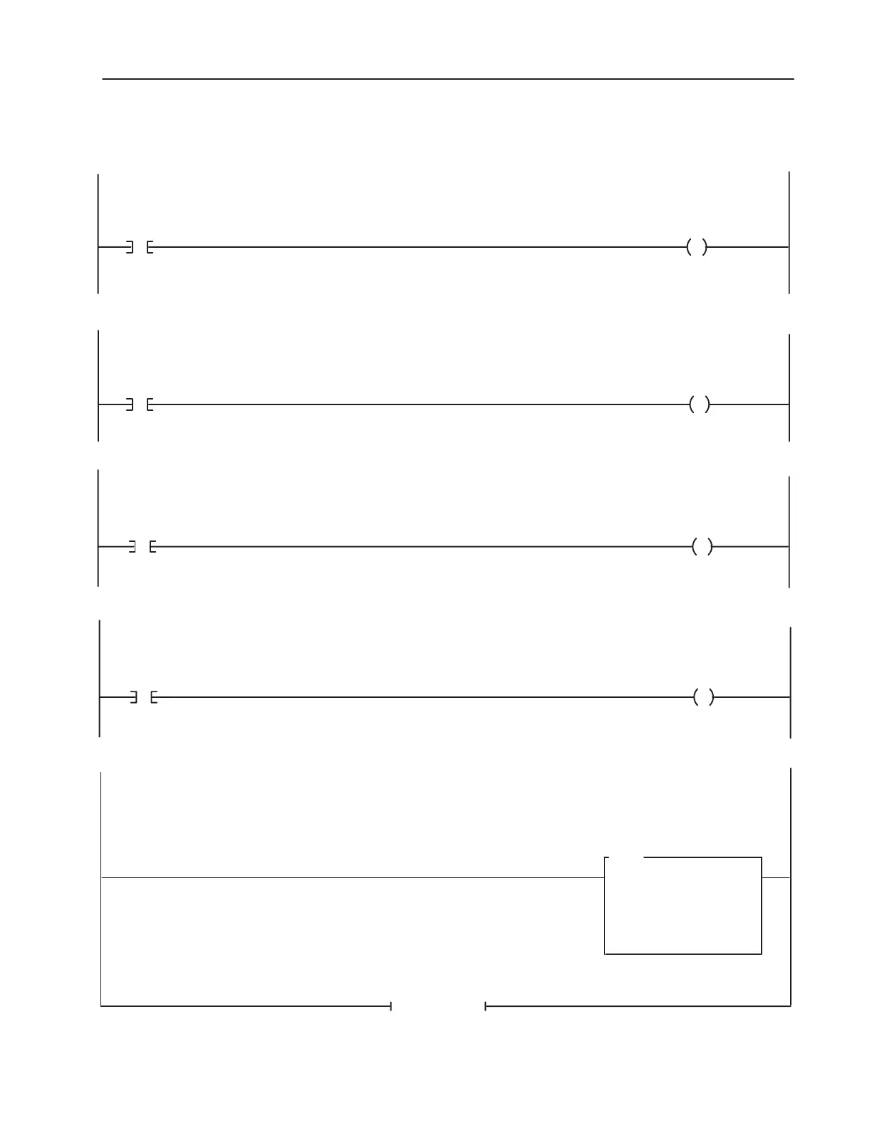
SLC 5/02 Example continued
When the Machine JOG Pushbutton is pressed, the PLC will send a JOG command to the drive. (Jog button is a normally open contact in this
example.)
When the drive is faulted, the PLC will receive a Drive Faulted Status Bit.
Drive Data In A1
(Data to Drive)
N7 : 1
500
0: 1.18
0
MOV
MOVE
Source
Dest
When the Machine Clear Faults Pushbutton is pressed, the PLC sends a Clear Faults command to the drive. (Clear Faults button is a momentary nor-
mally open contact in this example.)
Drive
Clear Faults
Command
0 : 1.16
Machine Clear
Faults
Pushbutton
I : 1.8
3
3
When the Drive is running, the PLC will receive a Drive Running Status Bit.
Machine
Running
Indicator
0 : 1.8
Drive
Running
Status Bit
I : 1.16
1
1
Drive
JOG
Command
0 : 1.16
Machine
JOG
Pushbutton
I : 1.8
2
2
END OF FILE
Machine
Faulted
Indicator
0 : 1.8
Drive
Faulted
Status Bit
I : 1.16
7
7
This rung moves a value from the PLC data table into the drive parameter specified by the Data In A1 parameter of the drive.

 Loading...