3–10 Configuration and Interfacing
Publication 1203–5.1 –– July, 1997
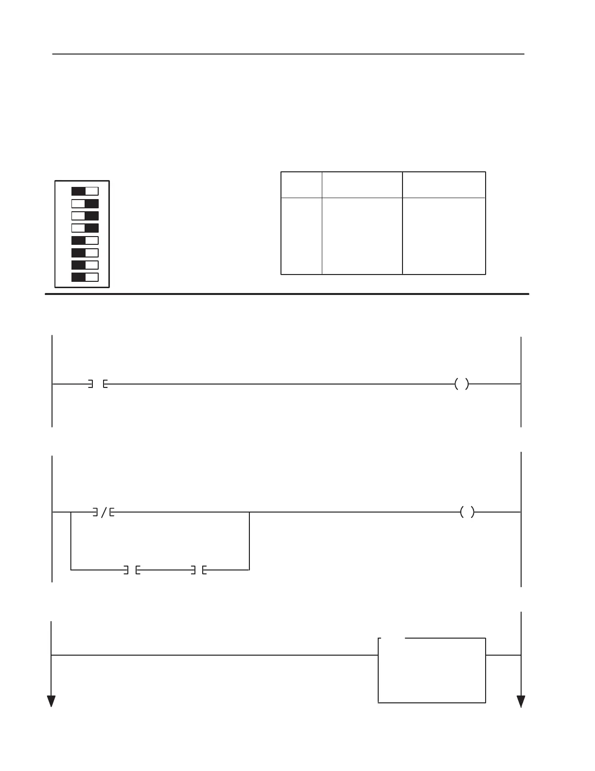
Figure 3.8
SLC 5/02
TM
Controller Example
Example Information:
PLC Type – SLC 5/02
Drive Type – 1336 PLUS
Drive Rack Address – 2
Rack Size
– 1/2 Rack Minimum
Starting Module Group – 0
When the Machine Start PushButton is pressed, the PLC sends a START command to the drive. The drive will start if no STOP command is being sent
by the PLC or any other control device. (Start button is a normally open contact in this example.)
Machine
START
Pushbutton
I : 1.8
0
Drive
START
Command
0 : 1.16
1
When the Machine Stop Pushbutton is pressed, the PLC sends a STOP command to the drive. (Stop button is normally closed contact in this
example).
This rung transfers a frequency command from the PLC data table to the drive. A range of 0 to 32767 is equivalent to Zero
to Maximum Frequency. (In this example, the drive’s Frequency Select parameters are set to receive a frequency reference from the RIO Adapter.)
Drive Frequency
Command
Machine
STOP
Button
I : 1.8
1
Drive
STOP
Command
0 : 1.16
0
0
Drive Stop
Command
0 : 1.16
1
Drive Running
Bit
I : 1.16
N7 : 0
16000
0: 1.17
16000
MOV
MOVE
Source
Dest
PLC
WORD
OUTPUT
IMAGE
INPUT
IMAGE
0
1
2
3
Logic Cmd
Reference
Datalink A
Datalink A
Logic Sts
Feedback
Datalink A
Datalink A
PLC Image Table Map
12345678
OPEN
Datalink B Off
Datalink C Off
Datalink D Off
Truncate Last Datalink Off
Datalink A On
Reference/Fdbk On
Logic Cmd/Sts On
Block Transfer Off
AB0508A

 Loading...