Overview 1–5
1336-GM1 Board Hardware
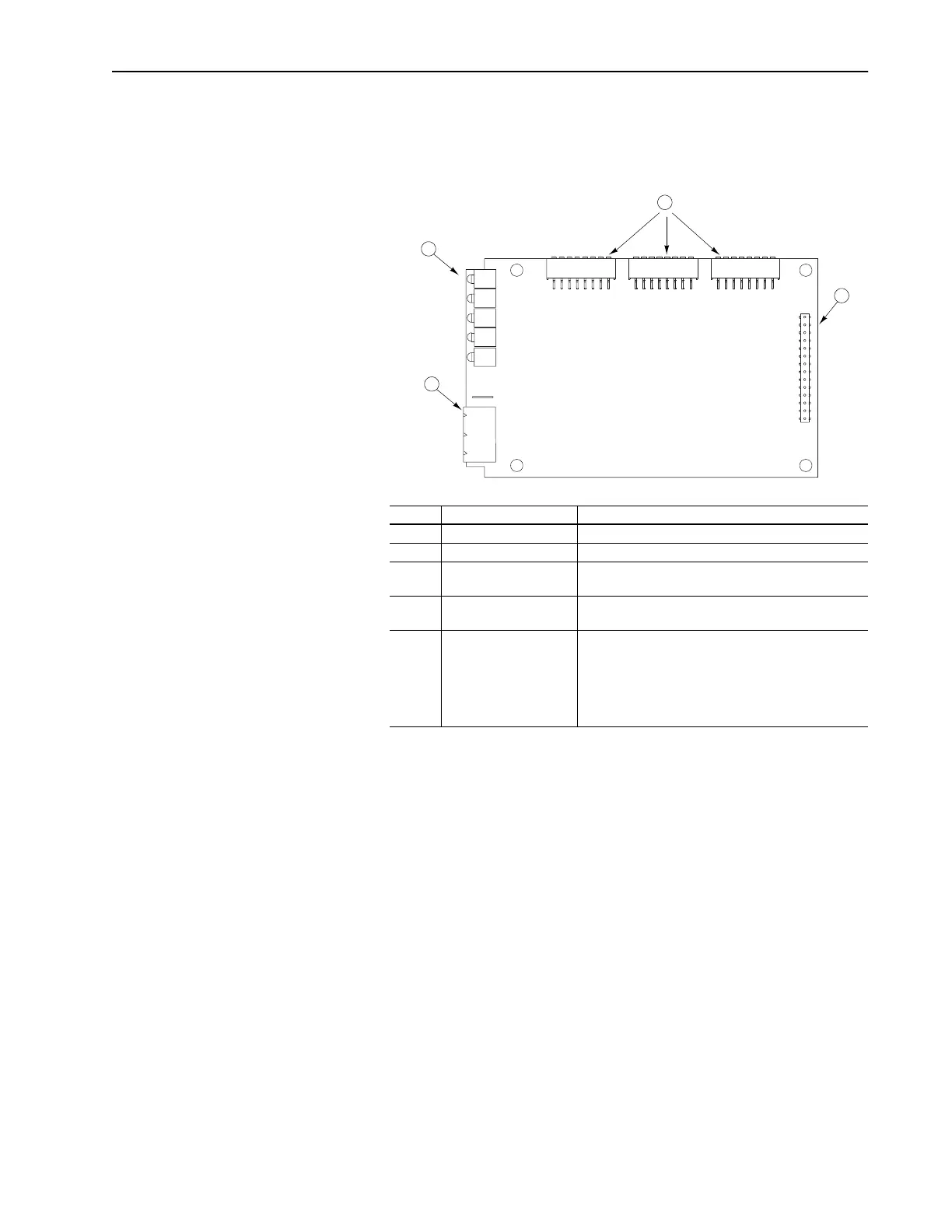
Figure 1.4 illustrates the main parts of a 1336-GM1 board.
Figure 1.4 Parts of the 1336-GM1 Board
# Part Description
1 SCANport Connection Internal 14-pin female SCANport connector.
2 Remote I/O Connection Standard 3-pin Remote I/O connector.
3 LEDs Status indicators for the module, SCANport connection,
and Remote I/O connection. Refer to Chapter 6.
4 DIP Switches Switches used to configure the module. Refer to
Chapter 2.
Not
Shown
Kit Materials for mounting the board to the SCANport prod-
uct. These material include one grounding wrist strap,
four Phillips mounting screws, four stand-off nylon head-
ers, one 3-pin Remote I/O connector, one snap-in comm
housing with mounting instructions, and termination
resistors.
3
4
1
2
Artisan Scientific - Quality Instrumentation ... Guaranteed | (888) 88-SOURCE | www.artisan-scientific.com

 Loading...


