Installing the Module 3–3
Installing a 1203-GD1 or
1203-GK1 Module
Required Tools and Equipment
To install your module, you need the following tools and equipment:
• Remote I/O communications module (1203-GD1 or 1203-GK1).
• 35 x 7.5 mm DIN rail.
• Appropriate cables for SCANport and Remote I/O connections.
Refer to the “Selecting Cables” section in this chapter.
• Termination resistor (if necessary). Refer to the “Selecting a
Termination Resistor” section in this chapter.
• 115 V/230 V AC or 24 V DC power supply.
Installing the 1203-GD1 or 1203-GK1 Module
1. Remove power from the Remote I/O link.
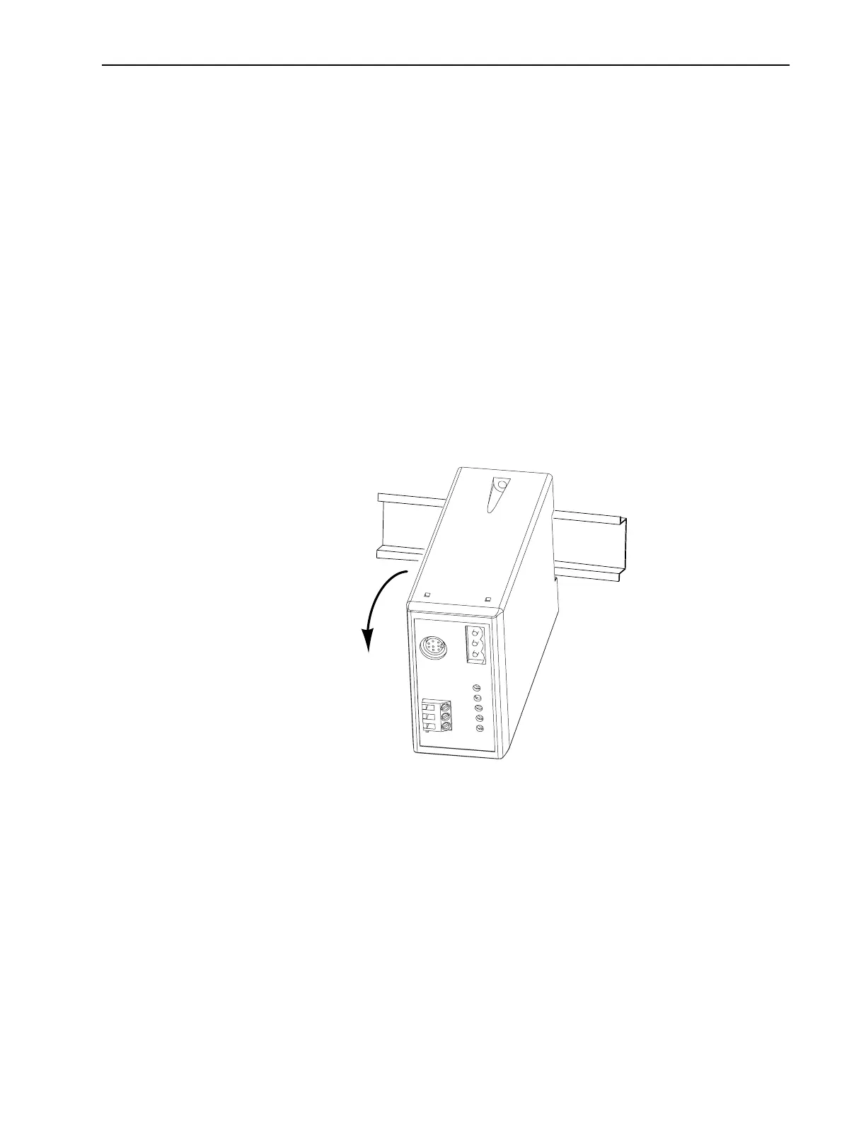
2. Hook the top lip of the module DIN rail mount onto the top of the
DIN rail and then rotate the module onto the DIN rail. It snaps
into a locked position.
Figure 3.1 Mounting a Module onto the DIN Rail
Artisan Scientific - Quality Instrumentation ... Guaranteed | (888) 88-SOURCE | www.artisan-scientific.com

 Loading...


