4–2 Creating Ladder Logic Programs
DIP switches on SW3 determine how the data contained in the
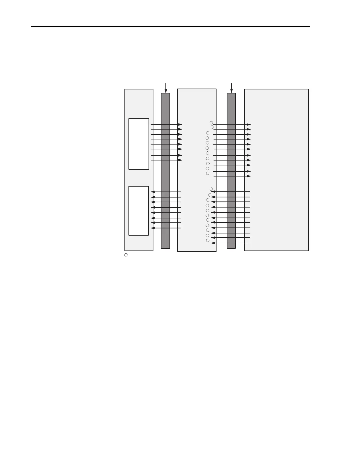
programmable controller I/O image table is used in the drive. Figure
4.1 shows an I/O image table.
Figure 4.1 I/O Image Table
Control Features
SW 3.1 through SW 3.3 select the basic control features: Block
Transfer, Logic Command/Status, and Reference/Feedback. When
enabled, each of these features adds one word to the input I/O image
table and one word to the output I/O image table.
Datalinks
SW 3.4 through SW 3.8 enable or disable the datalinks.
Description
A datalink is a type of pointer used by some SCANport products to
transfer data to and from the controller. Datalinks allow a parameter
value to be changed without using a block transfer message. When
enabled, each datalink consumes two 16-bit words in both the input
and output image table of the controller. When SW3.8 is ON, the last
datalink is truncated so that it uses only one word in the input and
output image table.
Remote I/O
Communications
Module
Block Transfer
Logic Command
Reference
Datalink A1
Datalink A2
Datalink B1
Datalink B2
Datalink C1
Datalink C2
Datalink D1
Datalink D2
Block Transfer
Logic Status
Feedback
Datalink A1
Datalink A2
Datalink B1
Datalink B2
Datalink C1
Datalink C2
Datalink D1
Datalink D2
SCANport Product
Controller
Image
Output Image
O:010
O:011
O:012
O:013
O:014
O:015
O:016
O:017
I:010
I:011
I:012
I:013
I:014
I:015
I:016
I:017
Input Image
Message Handler
Logic Command
Reference
Data In A1
Data In A2
Data In B1
Data In B2
Data In C1
Data In C2
Data In D1
Data In D2
Message Handler
Logic Status
Feedback
Data Out A1
Data Out A2
Data Out B1
Data Out B2
Data Out C1
Data Out C2
Data Out D1
Data Out D2
Remote I/O SCANport
8 words maximum
8 words maximum
1
1
1
1
1
1
1
1
1
1
1
1
1
1
1
1
1
1
1
1
1
1
1
Optionally enabled using DIP switches on the module. Refer to Chapter 2.
Artisan Scientific - Quality Instrumentation ... Guaranteed | (888) 88-SOURCE | www.artisan-scientific.com

 Loading...


