1–4 Overview
Hardware Description
The hardware included with the module depends on the module that
you have.
1203-GD1 and 1203-GK1 Modules
The 1203-GD1 module and 1203-GK1 module share the same parts.
Figure 1.3 illustrates these parts.
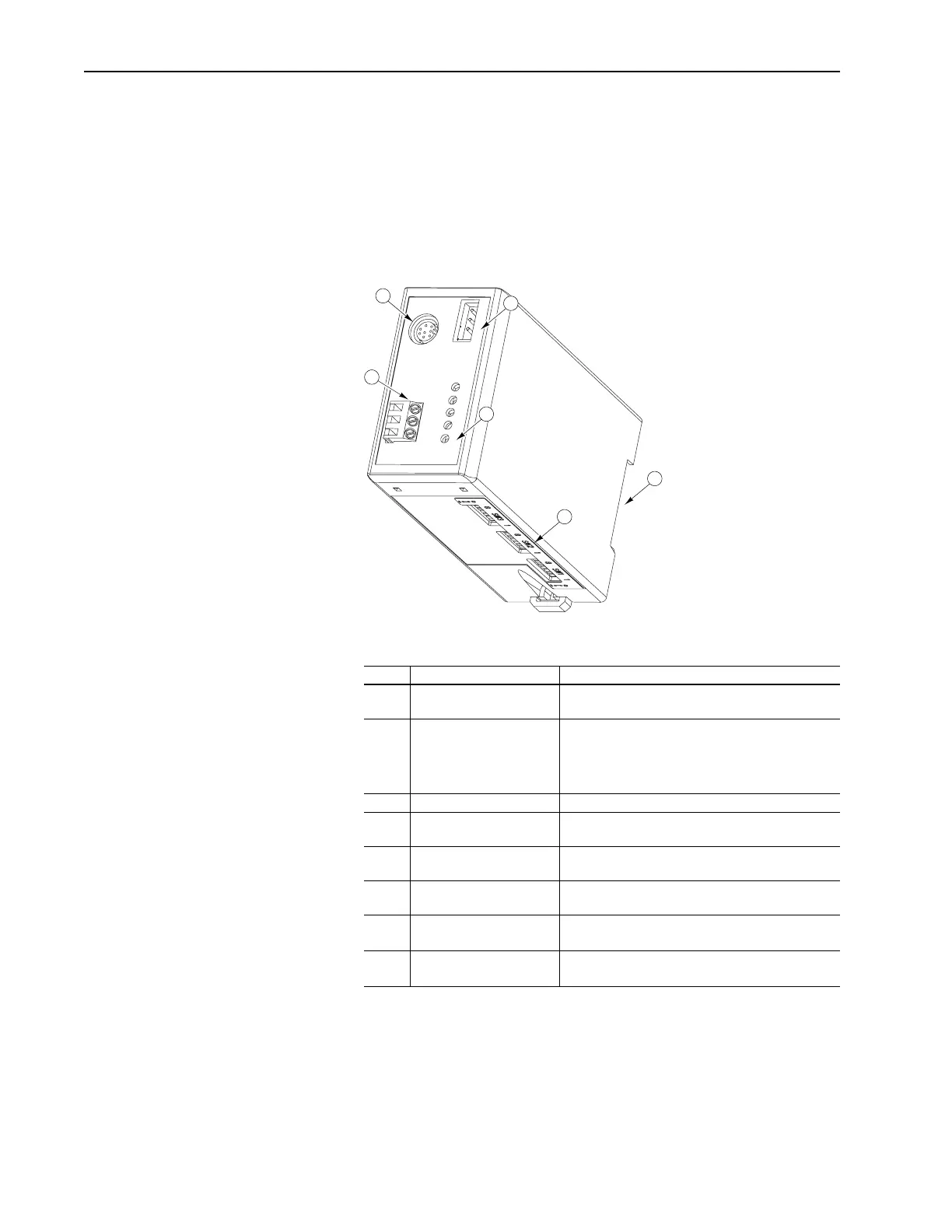
Figure 1.3 Parts of the 1203-GD1 and 1203-GK1 Module
# Part Description
1 SCANport Connection Standard SCANport 8-pin mini-DIN connector for the
SCANport cable.
2 Power Supply Connections Connections for the power supply. Multiple connec-
tions allow daisy-chaining.
The 1203-GD1 module uses 85 – 264V AC.
The 1203-GK1 module uses 24V DC.
3 Remote I/O Connection Standard 3-pin Remote I/O connector.
4 LEDs Status indicators for the module, SCANport connec-
tion, and Remote I/O connection. Refer to Chapter 6.
5 DIP Switches Switches used to configure the module. Refer to
Chapter 2.
6 DIN Rail Mount Mount for securely attaching and electrically ground-
ing the module to a DIN rail.
Not
Shown
Remote I/O connector One 3-pin connector for connecting the Remote I/O
cable to the module.
Not
Shown
Termination Resistors Two termination resistors for terminating the I/O link at
its physical ends. Refer to Chapter 3.
1
2
6
3
4
5
Artisan Scientific - Quality Instrumentation ... Guaranteed | (888) 88-SOURCE | www.artisan-scientific.com

 Loading...


