Installing the Module 3–5
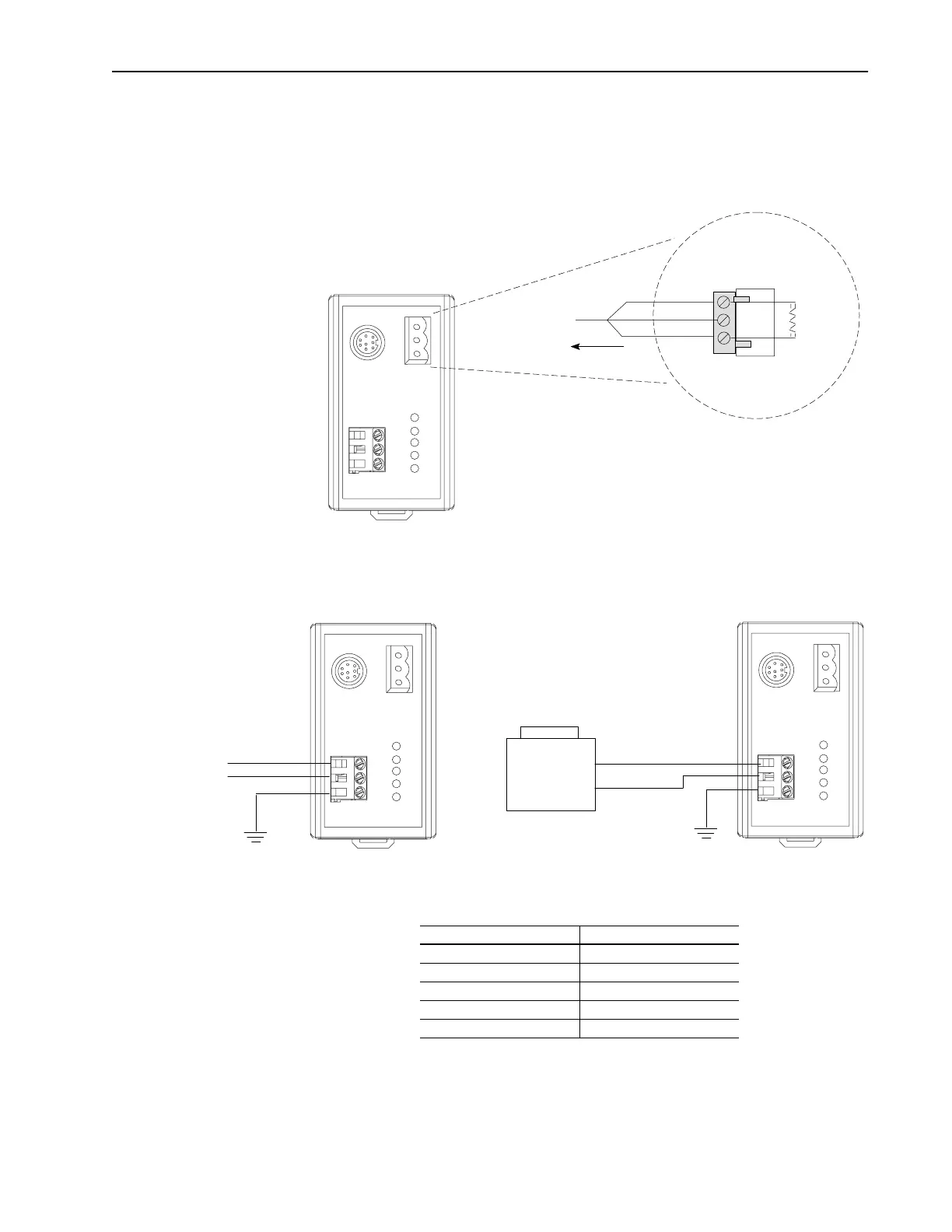
5. If the module is the last device on the Remote I/O link, connect
the termination resistor. If the Remote I/O link uses 230Kbps,
you must use an 82 ohm termination resistor.
Figure 3.4 Connecting the Termination Resistor
6. Connect the power supply to the module.
Figure 3.5 Connecting the Power Supply
7. Apply power to the Remote I/O link. The module is now
installed. Its LEDs are as follows:
You are now ready to create a ladder logic program.
Important:
If your LEDs are different, refer to Chapter 6.
Blue
Shield
Clear
To
Another Remote I/O
Link Device
1
2
I50 Ohm
or
82 Ohm
1 watt
+/-10%
Sh
GND
Hi 115V/230V AC
Low 115V/230V AC
GND
24V DC
Supply
-
+
L
N
G
+
-
G
1203-GD1 Module
1203-GK1 Module
LED Status
Fault Red (Blinking)
SCANport STS Green or amber
➀ ➁
Health Green or amber
➁
Rem I/O ACT Off
Rem I/O STS Off
➀
This LED is off if the module use firmware 2.xx or lower.
➁
Early versions of the module use amber LEDs.
Artisan Scientific - Quality Instrumentation ... Guaranteed | (888) 88-SOURCE | www.artisan-scientific.com

 Loading...


