62 Rockwell Automation Publication 1791ES-UM001G-EN-P - November 2016
Chapter 3 Install the Module
Table 20 - Recommended I/O Connector Cables
See http://www.ab.com/en/epub/catalogs/6005557/6005561/6125318/
8613745/8613769/8613771/Introduction.html for additional information.
Label the IP Address and Device Connections
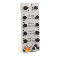
The 1732ES module ships with 12 white labels that you can use to identify the
IP address of the module, and the input and output connections. There are six
areas on the module to place the labels, with six additional labels that can be
used if the IP address or device connections change.
Use a pen or indelible marker with a fine tip to write on the labels. You can also
use a printing device to print the data onto the label. Contact a Brady
representative at http://www.bradyid.com
and ask about printer compatibility
for part number PTLEP-171-593.
Description Cat. No.
M12 right-angle male to flying leads cordset 889D-E5AC-2
(1)
(1) Replace -2 (2 m [6.6 ft]) with -5 (5 m [16.4 ft]) or -10 (10 m [32.8 ft]) for additional standard cable lengths.
M12 straight-male to flying leads cordset 889D-M5AC-2
(1)
M12 right-angle male to straight female patchcord 889D-F5ACDE-2
(2)
(2) Replace -2 (2m [6.6 ft]) with -OM3 (0.3 m [1.0 f t]), -1 (1 m [3.3 ft]), -5 (5 m [16.4 ft]), or -10 (10 m [32.8 ft]) for additional
standard cable lengths.
M12 straight male to straight female patchcord 889D-F5ACDM-2
(2)
IMPORTANT: Be sure that the
surface of the module is clean
and dry before you apply the
labels to the module.
Apply two labels here to identify
the IP address of the module.
Apply one label between each
pair of I/O connectors.
On the left side of the label,
identify the signal assignment to
the I/O connection on the left
side of the module.
On the right side of the label,
identify the signal assignment to
the I/O connection on the right
side of the module.

 Loading...


