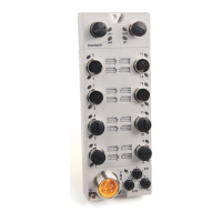
Do you have a question about the Allen-Bradley 1732ES-IB8XOBV4 and is the answer not in the manual?
| Product Type | I/O Module |
|---|---|
| Digital Inputs | 8 |
| Digital Outputs | 4 |
| Input Voltage Category | 24V DC |
| Output Voltage Category | 24V DC |
| Voltage Rating | 24V DC |
| Communication | EtherNet/IP |
| Mounting Type | DIN Rail |
| Output Type | Sourcing |
| Enclosure | IP67 |
| Operating Temperature | -20°C to 55°C |
Describes configuring dual-channel modes and discrepancy time for redundant safety devices.
Lists precautions for installation, testing, personnel training, and module handling.
Warns about electrical arcs and explosions when connecting/disconnecting wiring under power.
Specifies requirements for DC power supplies to prevent electric shock and module damage.
Provides guidelines and pin descriptions for wiring 1791ES modules' power and I/O connectors.
Provides pin descriptions and recommended cables for 1732ES modules' power and I/O connectors.
Provides wiring examples for various safety categories, including device connections and safety levels.
Shows wiring and controller configurations for specific applications like emergency stop switches.
Explains how to set the module's IP address using rotary switches on the device.
Details the process of adding modules to the I/O configuration tree in the programming software.
Guides on configuring general module properties like name, description, and safety network number.
Guides on configuring safety connections, including Requested Packet Interval (RPI) and CRTL.
Details how to configure module inputs, including operation type, point mode, and delay times.
Explains how to configure test output modes like Not Used, Standard, Pulse Test, Power Supply, and Muting Lamp.
Provides detailed technical specifications for 1791ES modules, including input/output characteristics.


