90 Rockwell Automation Publication 1791ES-UM001G-EN-P - November 2016
Chapter 5 Configure the I/O Modules
• Standard - Safety input has a standard field device that is wired to it
4. Complete entries, and note the following:
• For each safety input on the module, you can define if the input is
pulse tested. If the inputs are pulse tested, select which test source to
use.
• Off -> On and On -> Off delay times can be configured per channel
with each channel tuned to match the characteristics of the field
device for maximum performance.
• Input Error Latch Time is the time that the module holds an error to
make sure that the controller can detect it. This setting provides you
more reliable diagnostics and enhances the chances that a nuisance
error is detected.
5. Click OK at the bottom of the dialog box or a tab at the top of the dialog
box.
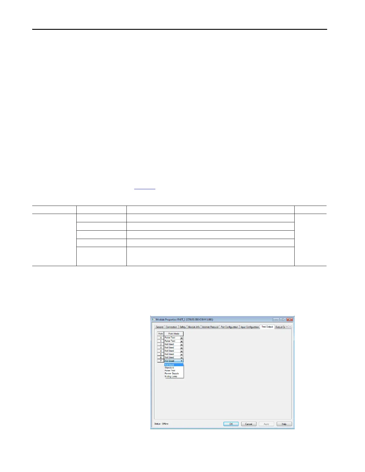
Configure the Test Outputs
Table 24 provides information for configuring the test outputs.
Follow these steps to configure the test outputs.
1. Click the Test Outputs tab.
Table 24 - Configuring Test Outputs
Parameter Name Value Description Default
Test Output Mode Not Used The test output is disabled. Not Used
Standard The output point is enabled for use by the GuardLogix controller.
Pulse Test The test output is being used as a pulse test source.
Power Supply A constant 24V is placed on the output terminal. It can be used to provide power to a field device.
Muting Lamp Output
(1)
An indicator lamp is connected to the output. When this lamp is energized, a burned-out bulb, broken
wire, or short to GND error condition can be detected. Typically, the lamp is an indicator that is used in
light curtain applications.
(1) Terminal T3/T7 for 1791ES-IB8XOBV4, 1732ES-IB8XOB8 and 1732ES-IB8XOBV4 modules, terminal T3/T7/T11/T15 for 1791ES-IB16 and 1732ES-IB16 modules, and terminal T3/T7/T11 for
1732ES-IB12XOB4 and 1732ES-IB12XOBV2 modules.
 Loading...


